BC Robotics
Browse categories
- New Additions
- Shop
- On Sale / Clearance
- Popular Categories
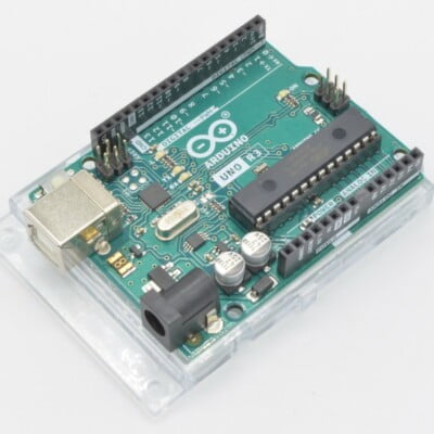
- ArduinoArduino is the most popular open source microcontroller platform on the market. These easy to program devices can read sensors, control relays, light up LEDs, and even talk to one another. Their ability to interact with the real world by way of sensors and other electronics makes them ideal for automation such as watering a plant when it is dry, reading the weather, or controlling lights when it gets dark – the possibilities are endless. We carry a variety of Arduino compatible microcontrollers from several manufacturers, each with their own specific strengths and purposes. To further specialize your microcontroller, we carry a large selection of daughter boards (shields) which can add powerful sensors, GPS, or even LCD screens to your project! Just getting started with microcontrollers? We carry a variety of Arduino starter kits to get you reading sensors and blinking lights as easily as quickly as possible!
- BBC micro:bitThe BBC micro:bit is a pocket-sized computer designed for beginners in electronics and coding. The micro:bit makes getting into these often daunting fields as easy as possible. Programming the micro:bit V2 can be done by computer or by their intuitive app available for Android and iOS devices. Code can be designed using a drag and drop interface in the Blocks editor, Javascript, or Python.
- ESP8266 & ESP32The ESP8266 and ESP32 microcontrollers from Espressif are powerful, inexpensive, and feature integrated WiFi connectivity. These are ideal for IoT applications. We offer a variety of different ESP8266 and ESP32 modules for different skill levels.
- FeatherFeather is a flexible and powerful family of microcontroller main-boards (Feathers) and daughter-boards (Wings) designed with portability in mind. All Feathers have integrated battery connectors (and most have built in lipo chargers) The Feather form factor is not locked to a specific chipset or programming language. Feathers are available with a variety of chipsets and on-board features. Most Feathers and FeatherWings have example code and libraries written in Arduino C/C++ and CircuitPython.
- Makey MakeyThe Makey Makey kit is a electronics kit designed for beginners. It explores the concepts of creating circuits through everyday items. When plugged into a computer you can use the Makey Makey to make anything into a keyboard or mouse. No programming required! Projects like a Banana Drum Set, Cat Detector, Musical Stairs, and countless others are easier than you think! We carry the Makey Makey Classic Kit – a starter kit for the Makey Makey – along with extra alligator clips, copper conductive tape, and replacement cables.
- Raspberry PiThe Raspberry Pi was first introduced in early 2012 as a simple, low cost, computer fit onto a circuit board roughly the size of a credit card. The idea was to use this low cost computer to promote teaching of computer science in schools but it has grown to be so much more! Since its release, well over 30 million of these little computers have been sold. We have carried the Raspberry Pi in Canada since it first became available and have watched as the Pi has morphed into a complete development platform with powerful single-board computers, cameras, touchscreens, and other accessories. Its multitude of inputs and outputs for electronics and computer peripherals and its impressive computing power mean it can be used to make just about anything you can imagine. The newest and most powerful version, the Raspberry Pi 4, is now available!
- Popular Brands
- AdafruitAdafruit was founded in 2005 by MIT engineer, Limor “Ladyada” Fried. Her goal was to create the best place online for learning electronics and making the best designed products for makers of all ages and skill levels. In the last 10 years, Adafruit has grown to over 100+ employees in the heart of NYC with a 50,000+ sq ft. factory.
- ArduinoArduino is an ever growing platform used by some of the most popular microcontrollers out there. For many of us, this is where it all started – the Arduino was (and still is today) a pioneer when it comes to making programming hardware easy and accessible. We have one of the largest selections of Arduino and Arduino accessories in Canada. These range from basic Arduino Uno, to Cellular and WiFi connected devices perfect for the Internet of Things, and all the accessories needed to get them running!
- Micro:bitMicro:bit Educational Foundation are the manufacturers of the popular BBC micro:bit; a pocket-sized computer designed for beginners in electronics and coding. The micro:bit makes getting into these often daunting fields as easy as possible. Programming the micro:bit V2 can be done by computer or by their intuitive app available for Android and iOS devices. Code can be designed using a drag and drop interface in the Blocks editor, Javascript, or Python.
- BC RoboticsIn addition to stocking 2000+ unique items, we also manufacture our own accessories right here at BC Robotics. In 2014 we began developing our own widgets and add-ons for Arduino, Raspberry Pi, and general prototyping. This has now grown to over 80 different SKUs. Our boards are assembled in-house with top quality components. Many feature detailed tutorials or project guides to get you up and running as quickly as possible!
- Raspberry Pi
- SparkFunSince 2003, SparkFun has been helping turn ideas into reality – whether you’re creating a smart weather station, exploring the frontier of machine learning, building a robot for school or prototyping your first (or tenth) product. No matter your vision or skill level, our open source components, resources and online tutorials are designed to broaden access to innovative technology and make the road to a finished project shorter. We’re here to help you start something.
- Frequently Asked Questions
- My Account
- Wishlist
- Cart
Free Shipping - US & Canada @ $150 CAD
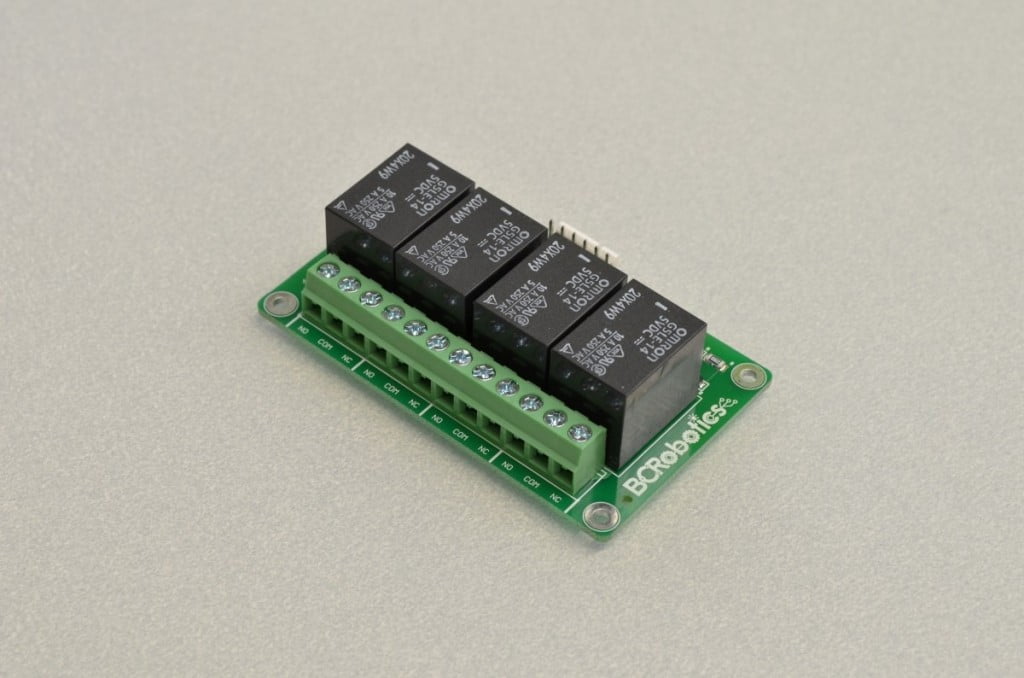
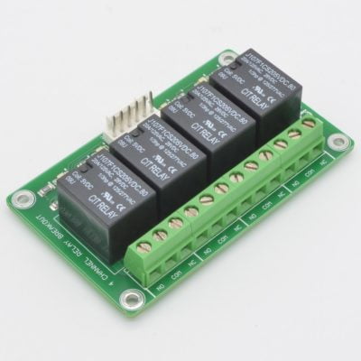
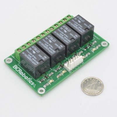
Getting Started With The 4 Channel Relay Breakout
PRODUCT TUTORIAL
- Chris @ BCR
- June 28, 2015
- 6:57 pm
- 12 Comments
The 4 Channel Relay Breakout is an easy way to use your Arduino, Raspberry Pi, or other microcontroller to switch high voltages and high current loads. The board is both 3.3V and 5V logic compatible and uses 4 digital outputs to control 4 individual relays. Each relay has the common, normally open, and normally closed pin broken out to a convenient 5.0mm pitch screw terminal. If this all sounds over your head, don’t worry, we will be going into this in great detail!
A Few Considerations:
Before we jump into getting this relay breakout board hooked up there are a few points to consider.
• While this board can be used to switch mains power, it should be done so using extreme caution. This should not be done without the aid of an experienced electrician.
• This board uses through hole components that could short if the board is placed on a conductive surface. We recommend this board be mounted using the four corner mounting holes before use.
How It Works:
This breakout takes care of all the extra components required to use a relay with a microcontroller. Each relay can be individually driven on this board; when one of the input pins is set high it will trigger a transistor that will trip the corresponding relay and illuminate an indicator light. Each input can be directly connected to an Arduino (or other microcontroller / single board computer) without worry of damage.
The Parts Needed:
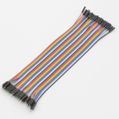
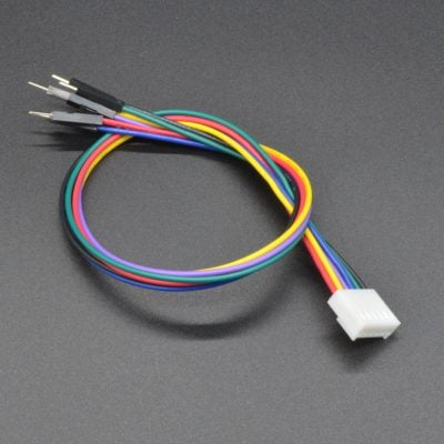
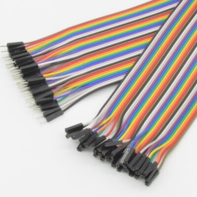
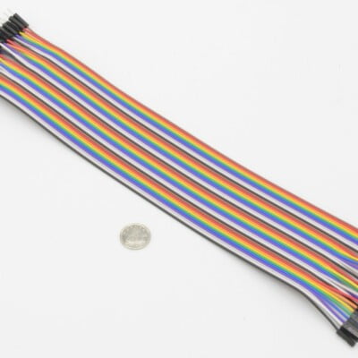
This tutorial will be requiring a few common parts:
View cart “Premium Female/Male Jumper Wires – 6″” has been added to your cart.
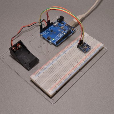
Step 1 - Power To The Breakout Board
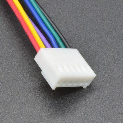
We manufacture a specific Molex Cable for this board, but you can also use standard jumper wires as well. We recommend using the Molex cable as it is keyed to prevent reverse insertion and has a locking ramp to prevent accidental removal.
Start by orienting the Arduino and 4 Channel Breakout Board next to one another. This breakout board operates on 5VDC, since the Arduino also runs on 5VDC we can take power off of the 5VDC pin on the Arduino.
Start by finding the “5V” pin on the Arduino and running a jumper wire over to the “VCC” pin on the breakout board. The VCC is the positive (power) input for the circuit. Next, run a wire from the “GND” (ground) pin on the Arduino to the “GND” pin on the Breakout Board.
The breakout board now has power!

14.3%
Step 2 - Connecting The Trigger Wires
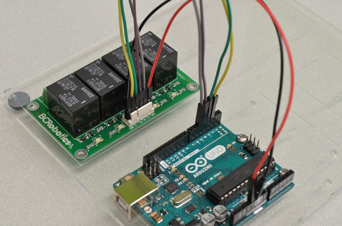
Each relay on the breakout board has an individual trigger wire meaning they can all be individually switched on and off. When each trigger wire has between 3 and 5VDC applied a transistor triggers the relay coil, in turn, making the relay switch. We can connect a digital pin from the Arduino to each of the trigger pins on the Arduino Uno to control the relays.
Let’s go ahead and connect Arduino to the breakout board. We will start with digital pin 2 as pins 0 and 1 are reserved for the Arduino’s Serial Port. Arduino Digital Pin 2 can be connected to the pin marked “1” on the relay breakout board, Arduino pin 3 to “2”, Arduino pin 4, to “3”, and Arduino pin 5 to “4”.
28.6%
Step 3 - Double Check And Plug It In!
Before we give the Arduino power it is always a good idea to go over all of the connections to make sure there are no wires in the wrong spot – sometimes that can make for a very expensive mistake!
One way to avoid this problem is good wire color discipline. In other words, decide on a purpose for each color of wire and stick to them! In this example all 5V power are red wires, all grounds are black wires, and other colors are signal wires. If you are using our 6 Pin Molex Cable with this board, this is already taken care of! This way, if you ever see a red wire going to a black wire you will know right away that something isn’t quite right!

42.8%
Step 4 - Starting The Code
					void setup() {
// put your setup code here, to run once:
}
void loop() {
// put your main code here, to run repeatedly:
}
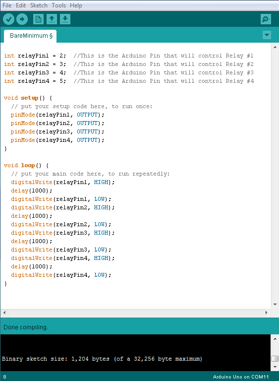
Now that we have finished with the hookup we need to start writing some code. We will be using the Arduino IDE, this is available from https://www.arduino.cc/en/Main/Software
We will start with the “BareMinimum” sketch found by clicking “File” and selecting Examples / Basic / BareMinimum. This sketch is a great starting point as it includes the Setup and Loop functions – we will write the rest!
57.1%
Step 5 - Understanding How To Control The Breakout Board
This breakout board is expecting to see a digital output signal on each of its 4 control pins so the code will be fairly simple to set up. When each Arduino pin is set “high” the connected relay will switch. When the Arduino pin is set “low” the relay will return to its off position.
Lets write a few lines of code and get this board up and running!
71.4%
Step 6 - Writing The Code
We are starting with the BareMinimum Sketch found in the IDE, it should look something like this:
					void setup() {
// put your setup code here, to run once:
}
void loop() {
// put your main code here, to run repeatedly:
}
So first we will need some variables for the Arduino pins we plan to use:
					int relayPin1 = 2; //This is the Arduino Pin that will control Relay #1
int relayPin2 = 3; //This is the Arduino Pin that will control Relay #2
int relayPin3 = 4; //This is the Arduino Pin that will control Relay #3
int relayPin4 = 5; //This is the Arduino Pin that will control Relay #4

void setup() {
// put your setup code here, to run once:
}
void loop() {
// put your main code here, to run repeatedly:
}
Basically we are going to reduce the opportunity for confusion later down the road by assigning names to each of the Arduino pins. Now, instead of trying to remember that Arduino Pin 2 is Relay number 1, we will simply just refer to the variable “relayPin1” instead – much easier!
Next we will set all of the pins we are using to be digital outputs:
					int relayPin1 = 2; //This is the Arduino Pin that will control Relay #1
int relayPin2 = 3; //This is the Arduino Pin that will control Relay #2
int relayPin3 = 4; //This is the Arduino Pin that will control Relay #3
int relayPin4 = 5; //This is the Arduino Pin that will control Relay #4

void setup() {
// put your setup code here, to run once:
pinMode(relayPin1, OUTPUT);
pinMode(relayPin2, OUTPUT);
pinMode(relayPin3, OUTPUT);
pinMode(relayPin4, OUTPUT);
}

void loop() {
// put your main code here, to run repeatedly:

}
Ok, now all of the pins are set to outputs. Next we can write some code in the loop to switch a relay on and off:
					int relayPin1 = 2; //This is the Arduino Pin that will control Relay #1
int relayPin2 = 3; //This is the Arduino Pin that will control Relay #2
int relayPin3 = 4; //This is the Arduino Pin that will control Relay #3
int relayPin4 = 5; //This is the Arduino Pin that will control Relay #4

void setup() {
// put your setup code here, to run once:
pinMode(relayPin1, OUTPUT);
pinMode(relayPin2, OUTPUT);
pinMode(relayPin3, OUTPUT);
pinMode(relayPin4, OUTPUT);
}

void loop() {
// put your main code here, to run repeatedly:
digitalWrite(relayPin1, HIGH); //Switch Relay #1 ON
delay(1000); //Wait 1 Second
digitalWrite(relayPin1, LOW); //Switch Relay #1 OFF
delay(1000); //Wait 1 Second
}
If we were to upload this code to the Arduino it will turn Relay #1 on for 1 second and then switch it off for 1 second and continue through this loop forever.
So before we do upload the code let’s use of all 4 relays to make a lot of clicking noise:
					int relayPin1 = 2; //This is the Arduino Pin that will control Relay #1
int relayPin2 = 3; //This is the Arduino Pin that will control Relay #2
int relayPin3 = 4; //This is the Arduino Pin that will control Relay #3
int relayPin4 = 5; //This is the Arduino Pin that will control Relay #4

void setup() {
// put your setup code here, to run once:
pinMode(relayPin1, OUTPUT);
pinMode(relayPin2, OUTPUT);
pinMode(relayPin3, OUTPUT);
pinMode(relayPin4, OUTPUT);
}

void loop() {
// put your main code here, to run repeatedly:
digitalWrite(relayPin1, HIGH);
delay(1000);
digitalWrite(relayPin1, LOW);
digitalWrite(relayPin2, HIGH);
delay(1000);
digitalWrite(relayPin2, LOW);
digitalWrite(relayPin3, HIGH);
delay(1000);
digitalWrite(relayPin3, LOW);
digitalWrite(relayPin4, HIGH);
delay(1000);
digitalWrite(relayPin4, LOW);
}
85.7%
Step 7 - Upload The Code And Test
Now that all of the code has been written it can be uploaded to your Arduino! Click “Upload” button in the top left corner of the Arduino IDE and it should upload without any issues. After a few seconds the relays should start turning on and off in order one after another at a 1 second interval.
100%
12 thoughts on “Getting Started With The 4 Channel Relay Breakout”
James Boag
By adding a very cheap Ethernet shield you can have the basis of your Internet of things, I am currently controlling my 12 volt garden lights and pond lights from a very similar set up. The Arduino runs the web server and these can be controlled from my phone or anything with a web browser.
Chris @ BCR
Very true, with a WiFi controlled relay a lot can be done. We have been working on a couple small, low cost, IoT boards for that specific purpose that should be rolling out very soon!
Albert
Hi James, im currently working on the same project using arduino, bluetooth module and relay board to turn off and lights using smart phone, i need some assistance in this, i will appreciate.
Patrice Boudreault
Here’s the holy grail of IoT:
1- Adafruit ESP8266 Huzzah (13$ wi-fi arduino microcontroller!)
2- RaspberryPi running:
– Mosquitto MQTT server, to handle messages between unlimited IoT devices in your house
– Apache web server, to provide user interface for all devices, with JavaScript websockets MQTT library.
Seriously, this setup makes adding new devices a breeze.
Marvin Pegg
when will you have part II, I want to program a controller for greenhouse temp. including exhaust fans and zone valves etc.
thanks
Marvin
Satish yadav
Arduino Bluetooth for chann
el code
Andries Roode
Hi Marvin,
I developed a Arduino system with a 128×64 screen that reads temp and displays on screen. It regulates 4 different fans, heaters and cooling pads according to the temp. It also has a clock module that gives me time and date to regulate valves and pumps for the plants in the greenhouse.
You can contact me on andries.roode@gmail.com
Mick
I’m using this relay board from switches on a 5v rail. The board is fed from 5v. Is this ok or do I need to add pull down resistors as the switches are push to make and floating when not closed? Thanks
William @ BC Robotics
Hi Mick,
No need to add anything
MJ
By connecting the same as above nothing happens. Why is that happening?
Chris @ BCR
Hi MJ,
If it is connected exactly as above and nothing is happening, feel free to get in touch with our support team – they can help diagnose if it may be a warranty issue. Just have your order number handy!
Cheers,
Chris
D Butler
Great tutorial. I want write a simple program that the next relay doesn’t trigger until a limit switch is triggered and loops through 4 sequences of doing this. Output would run a different motor until next limit switch is hit. Any suggestions of other tutorials that may help with this?