Controlling A DC Motor With Arduino
In this tutorial we will be using an Arduino to control the speed and direction of a DC Motor. For this tutorial we will be using our basic DC Hobby Motor but this tutorial can be applied to just about any DC Motor out there that falls within the peak voltage and current specifications of the H-Bridge we are using. Moving forwards, this hardware and code can be adapted to make a small driving robot.
A Few Considerations:
When choosing a DC motor it will need to be compatible with the motor controller chip that we are using. This Texas Instruments SN754410NE (A popular drop in replacement for the L293D) can supply a motor with between 4.5 and 36.0V at up to 1.0A. While the motor controller can handle up to 36V, the motor we are using has a maximum voltage is 9.0VDC so to keep things simple we will want to keep the motor power supply to a voltage less than that. This voltage range gives us quite a few options – we could power it from a wall power supply, bench power supply, AA batteries, or even a 9V battery! Feel free to use which ever appropriate supply you have laying around.
How It Works:
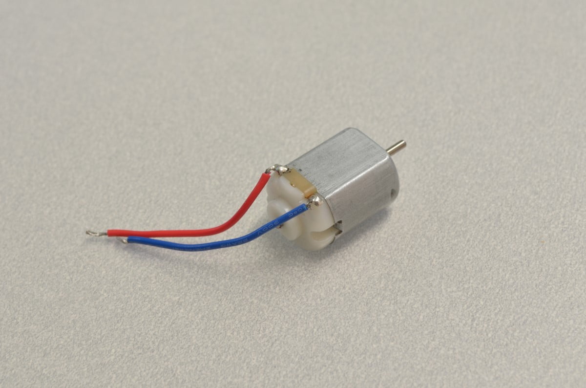
DC motors themselves are very simple; any basic DC Motor will have two leads that can be directly attached to a battery or power supply of sufficient capacity. The side of the motor that is connected to the positive of the power source will determine which way the motor rotates. Feel free to give this a try with the breadboard and power supply! We will be going a step further than this and using a motor controller called an H-Bridge. Rather than having to unplug the motor to reverse it, this clever chip allows us to reverse the polarity to the motor using logic level signals from a microcontroller. The motor can be run in each direction on command! The chip does all of the heavy lifting and can be directly connected to the DC motor and the Arduino, no additional parts are required!
The Parts Needed:
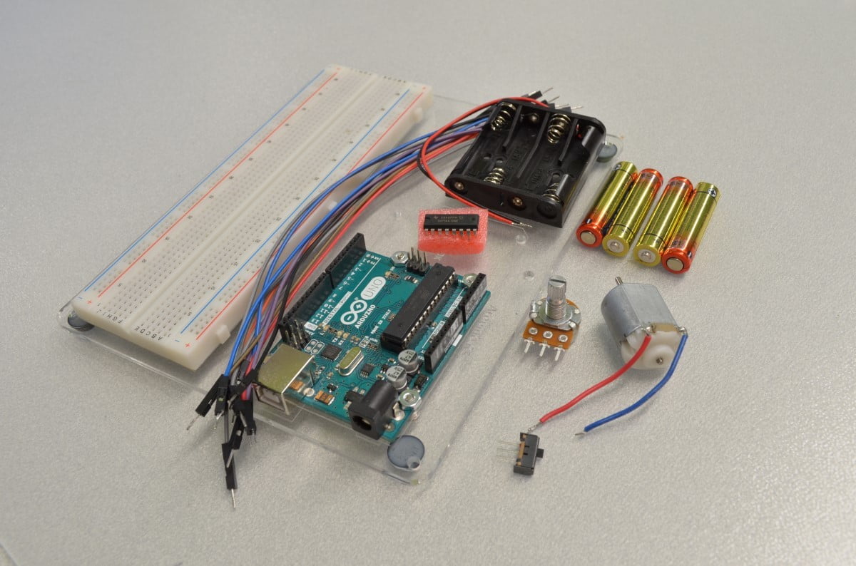
This tutorial will be requiring a few common parts:
[list type=”check”]
[/list]
We have also used one of our full sized Arduino Mounting Plates in this tutorial. The mounting plate keeps your Arduino and breadboard neatly fixed next to one another, allowing for much more organized prototyping!
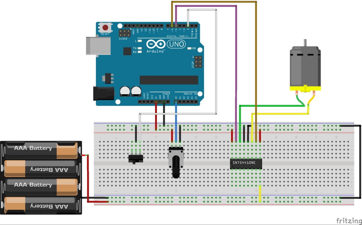
The Schematic
This handy little diagram shows how we will be connecting everything. Yes, it does look a little overwhelming but we will be going through this step by step!
Step 1 – Powering The Breadboard
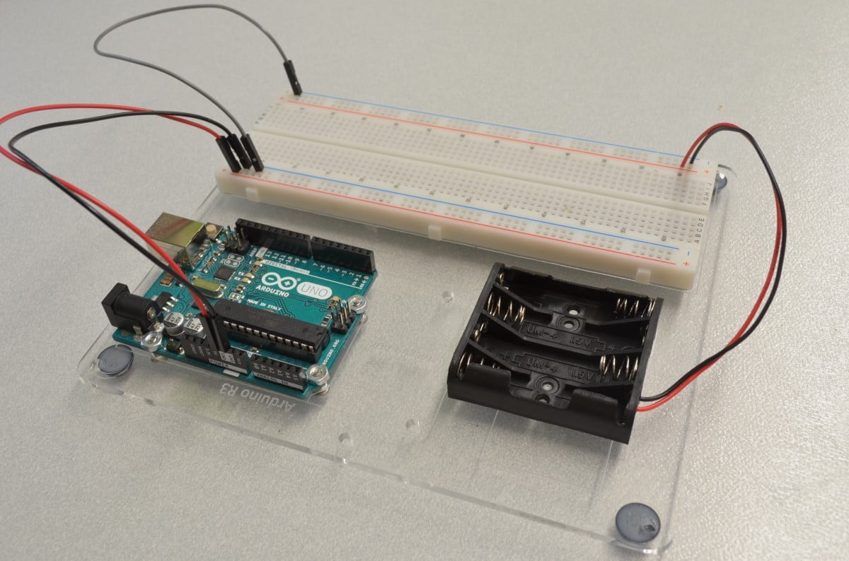
To simplify this tutorial we are going to use two different power supplies. The Arduino is going to be powered by the USB connection while the DC motor is going to be powered by a battery pack. While there are more efficient ways to do this, this will allow the tutorial to work with as many DC motors as possible. The motor power supply should be compatible with the DC motor. In our tutorial we are going to use our DC Hobby Motor which works with 4.5 to 9.0V DC and a battery case that holds 4 x AAA batteries (approximately 6VDC).
First, let’s get the power out of the way. Connect your motor power supply to one of the sets of common rails on the breadboard and connect the 5VDC and GND pins of the Arduino to the common rails on the opposite side of the breadboard as shown. We are also going to tie the ground rails together to form one large common ground between both power supplies.
Step 2 – The H-Bridge

The H-Bridge is probably the “scariest” part in this tutorial – they have a whole bunch of unlabelled pins and generally look complicated… so let’s get that out of the way next!
Insert the H-Bridge into the breadboard so that it bridges the middle of the breadboard. It is important to ensure it is placed facing the right direction so that our connections will all be made to the right locations on the chip. There is a “D” shaped indent on one end of the chip, this indicates which end pin 1 is located (Alternatively, chips can be marked with a small round indent or a white dot). With the breadboard sitting in front of you as pictured, ensure that the indent is on the left side. The pins on these chips are fairly delicate so be sure not to break them.
Step 3 – Wiring the H-Bridge
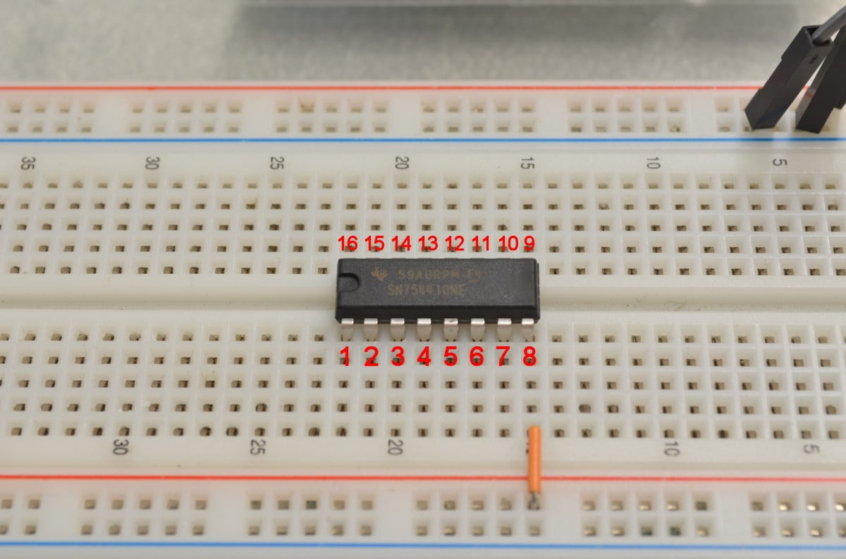
One of the questions always asked is: “How do we know what each pin on this chip does?” – Good Question, for that we are going to need the Datasheet. Datasheets tell you all sorts of information about a product; for Integrated Circuits like this they will give you a “Pinout” which shows what each pin does and where it is located on the chip. Since we know where Pin 1 is on the IC now, we can use the pinout (found on page 1 of the datasheet) to figure out the rest!
This H-Bridge is capable of driving two separate DC motors so we are only going to use half of the chip. Pins 1 – 7 can be left disconnected. Pin 8 Is our Motor Power Input so we are going to connect it directly to the battery power.
Step 4 – Wiring the H-Bridge: Part 2
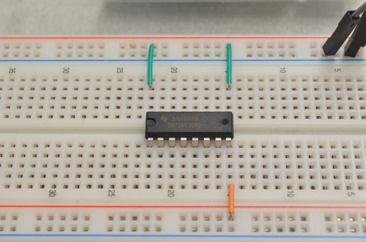
Both pins 9 and 16 need to be connected to 5VDC from the Arduino. Pin 9 is our “Enable” pin for output 3 and 4 – This enables the side of the motor controller we are using; for this tutorial just tie it directly to the 5VDC power from the Arduino so that it is permanently switched on. Pin 16 is our H-Bridge’s internal power.
Step 5 – Wiring the H-Bridge: Part 3
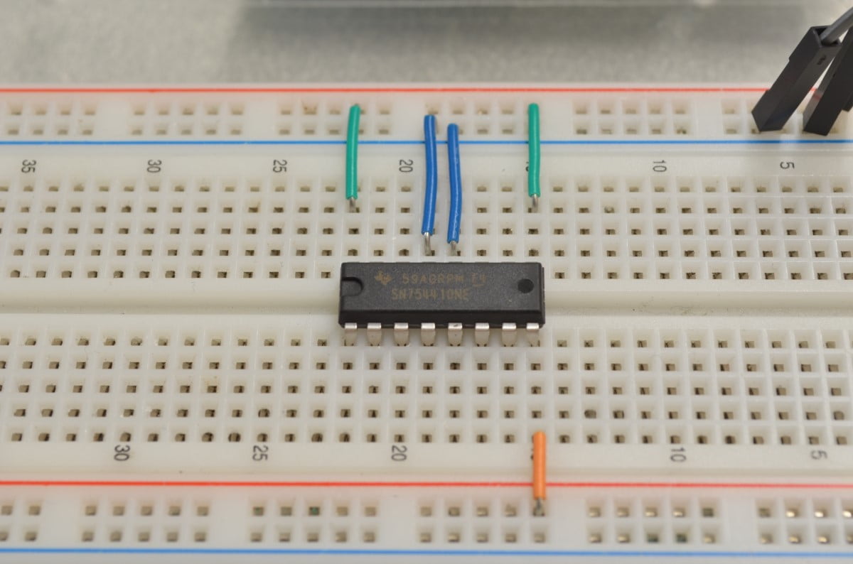
Next we will need to connect the ground pins to the common ground on the breadboard. Pins 4, 5, 12, and 13 are all tied together as a combination ground / heatsink for the chip. Since we are just using this in a breadboard we will connect 12 and 13 to the ground rail but feel free to connect all 4 pins.
Step 6 – Wiring the H-Bridge: Part 4
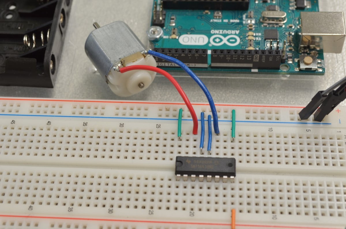
Next, we are going to wire in the motor to the output pins of the H-Bridge. It really does not matter which way these two wires are connected.
Step 7 – Wiring the H-Bridge: Part 5
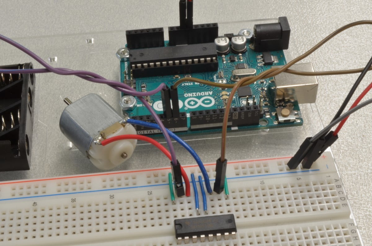
Finally, we will wire the two logic level input pins from the Arduino to the H-Bridge. We are using pins 5 and 6 on the Arduino. The wiring is getting a little crowded at this point so be sure not to knock anything out of place.
Step 8 – The Direction Switch
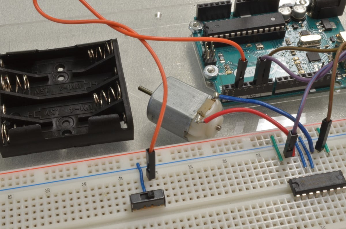
Right now we could program the Arduino and get the motor running but we wouldn’t have any way to tell the motor what to do… so we will hook up a potentiometer and a switch. The potentiometer will be used to control the motor speed and a small switch will control the direction the motor spins.
First, insert the breadboard friendly switch into the breadboard. The middle pin on the switch can be connected to ground while the right pin can be connected to Arduino Digital Pin #2 (White in the diagram)
Step 9 – The Potentiometer
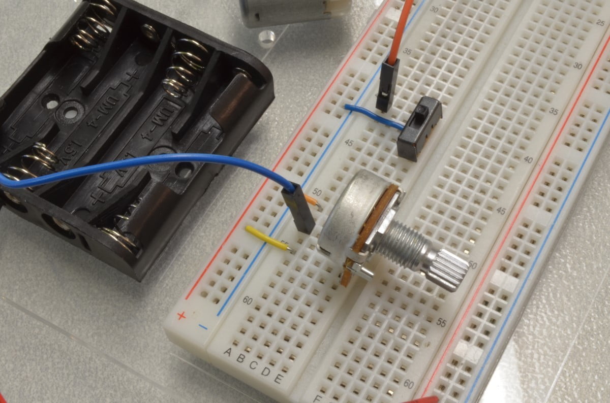
Next, insert the Potentiometer into the breadboard. It will need the left pin connected to 5V power from the Arduino and the right pin connected to ground. The middle pin can be directly connected to Arduino Analog Pin A0.
Step 10 – Double Check The Wiring!
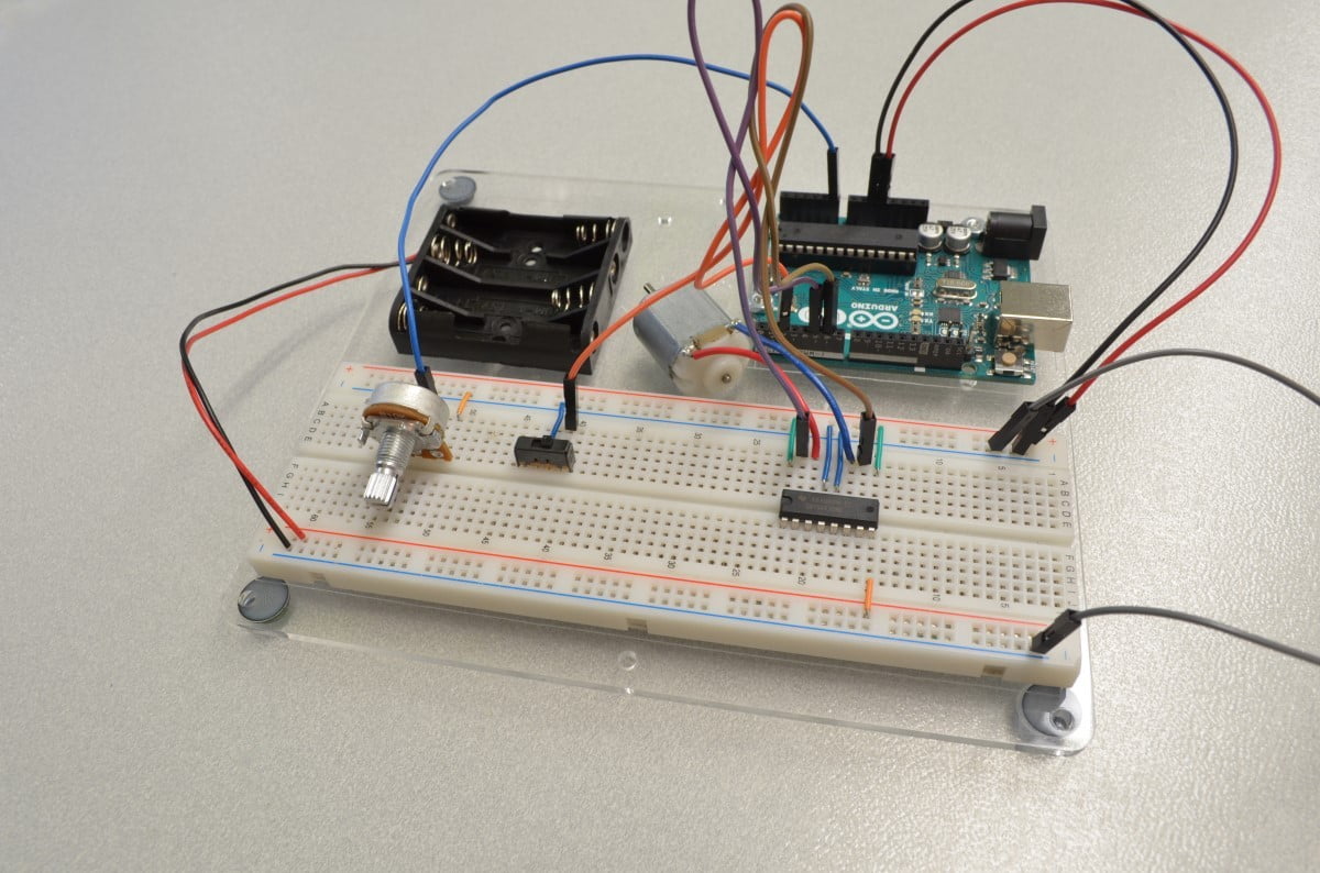
Before we give the Arduino power or plug in any motor power it is always a good idea to go over all of the connections to make sure there are no wires in the wrong spot – sometimes that can make for a very expensive mistake! For now, we will leave the batteries out while we program the Arduino.
Step 11 – Starting The Code
void setup() {

  // put your setup code here, to run once:

}

void loop() {

  // put your main code here, to run repeatedly:

}
Now that we have finished with the hookup we need to start writing some code. We will be using the Arduino IDE, this is available from https://www.arduino.cc/en/Main/Software
We will start with the “BareMinimum” sketch found by clicking “File” and selecting Examples / Basic / BareMinimum. This sketch is a great starting point as it includes the Setup and Loop functions – we will write the rest!
Step 12 – Understanding How To Control The DC Motor
The H-Bridge really does all of the heavy lifting in this circuit – and that makes driving the motor quite easy. On the other side of the circuit we are using two very easy components (A Potentiometer and a Switch) to create a simple user interface. The interface could very easily be swapped out with different sensors – maybe a photocell? or a temperature sensor? The possibilities are endless.
Excited? Let’s go write the code!
Step 13 – Writing The Code: Part 1
We are starting with the BareMinimum Sketch found in the IDE, it should look something like this:
[cpp]
void setup() {
// put your setup code here, to run once:
}
void loop() {
// put your main code here, to run repeatedly:
}
[/cpp]
So first we will need to create few variables for our switch and potentiometer:
[cpp highlight=”1, 2″]
int switchPinFwd = 2; //Input from the switch when in the Forward position
int potentiometerIn; //variable to hold the potentiometer input
void setup() {
// put your setup code here, to run once:
}
void loop() {
// put your main code here, to run repeatedly:
}
[/cpp]
Since we are not using an external pull-up resistor with the switch, we will need to set the internal pull-up through code:
[cpp highlight=”6″]
int switchPinFwd = 2; //Input from the switch when in the Forward position
int potentiometerIn; //variable to hold the potentiometer input
void setup() {
// put your setup code here, to run once:
pinMode(switchPinFwd, INPUT_PULLUP);
}
void loop() {
// put your main code here, to run repeatedly:
}
[/cpp]
Now that the digital inputs are set up, we will write a little code in the loop function to read the potentiometer and store it in the variable we created earlier. This will allow the program to update the current position of the potentiometer constantly.
[cpp highlight=”11″]
int switchPinFwd = 2; //Input from the switch when in the Forward position
int potentiometerIn; //variable to hold the potentiometer input
void setup() {
// put your setup code here, to run once:
pinMode(switchPinFwd, INPUT_PULLUP);
}
void loop() {
// put your main code here, to run repeatedly:
potentiometerIn = analogRead(A0);
}
[/cpp]
The variable potentiometerIn will store the value read from the potentiometer – this will range from 0 to 1023 and will be the basis of the speed control.
Step 14 – Writing The Code: Part 2
Continuing from the last section, where we prepared the inputs, we will now make use of them. First, let’s figure out if the motor is going forwards or reverse by reading the position of the switch. The switch is really quite simple, and because of the way we wired it, it will read HIGH when it is in the forward position. Since the switch only has one other position we can safely assume that when the pin reads LOW it will be in the reverse position. We will do this with an If Statement:
[cpp highlight=”13-20″]
int switchPinFwd = 2; //Input from the switch when in the Forward position
int potentiometerIn; //variable to hold the potentiometer input
void setup() {
// put your setup code here, to run once:
pinMode(switchPinFwd, INPUT_PULLUP);
}
void loop() {
// put your main code here, to run repeatedly:
potentiometerIn = analogRead(A0);
if(digitalRead(switchPinFwd) == HIGH) //Check to see if the pin is high or low
{
//If the pin is HIGH, it must be set to forward
}
else
{
//Otherwise the switch must be set to Reverse
}
}
[/cpp]
The If Statement works a little like a fork in the road. When the program hits this line it is going to make a decision based on the parameters in the brackets. In this case we are going to look at the switch and make a decision based on what position the switch is in and that will determine which way the motor will go. So IF the motor direction switch is set to forward it will run the code (that we have not written yet) to make the motor go forwards, otherwise (else) it will run the code to make it go backwards. Best practice? probably not – but good enough to get you experimenting.
So with all that being said, what code do we use to get the motor to move? Well that is where it gets a little more complicated. First we are going to have to set the output pin variables and change them to an Output in the setup function:
[cpp highlight=”4, 5, 11, 12″]
int switchPinFwd = 2; //Input from the switch when in the Forward position
int potentiometerIn; //variable to hold the potentiometer input
int fwdPin = 5; //Logic level output to the H-Bridge (Forward)
int revPin = 6; //Another logic level output to the H-Bridge (Reverse)
void setup() {
// put your setup code here, to run once:
pinMode(switchPinFwd, INPUT_PULLUP);
pinMode(fwdPin, OUTPUT); //Set the forward pin to an output
pinMode(revPin, OUTPUT); //Set the forward pin to an output
}
void loop() {
// put your main code here, to run repeatedly:
potentiometerIn = analogRead(A0);
if(digitalRead(switchPinFwd) == HIGH) //Check to see if the pin is high or low
{
//If the pin is HIGH, it must be set to forward
}
else
{
//Otherwise the switch must be set to Reverse
}
}
[/cpp]
Now we have some output pins that will tell the H-Bridge what to do. If the forward pin was set HIGH, the motor will now spin at full speed in a forward direction while setting the reverse pin HIGH would make it spin in reverse. Not exactly what we are going for, but close!
So how do you get different speeds? Without getting too technical, we are going to use a Pulse Width Modulated signal to control the speed of the motor. Instead of just setting the Forward or Reverse pin on, we are going to turn the pin on and off really quickly. As the ratio of “off” to “on” changes (also known as Duty Cycle), so does the speed of the motor.
Examples:
It all sounds complicated but fortunately the Arduino software has this solved with one line of code that will do everything we need! All we need to do is use
AnalogWrite(pin, value);
Inside the brackets, the value is supposed to be a number between 0 and 255. 0 will give you a 0% output, 255 will give you 100% output.
This is all starting to come together! Earlier we figured out that the potentiometer gives us a value between 0 and 1023 as an input. Now we have an output that needs a variable between 0 and 255. If we divide the potentiometer input by 4, that potentiometer input value can be fed directly to the AnalogWrite function to control the motor speed!
[cpp highlight=”18″]
int switchPinFwd = 2; //Input from the switch when in the Forward position
int potentiometerIn; //variable to hold the potentiometer input
int fwdPin = 5; //Logic level output to the H-Bridge (Forward)
int revPin = 6; //Another logic level output to the H-Bridge (Reverse)
void setup() {
// put your setup code here, to run once:
pinMode(switchPinFwd, INPUT_PULLUP);
pinMode(fwdPin, OUTPUT); //Set the forward pin to an output
pinMode(revPin, OUTPUT); //Set the forward pin to an output
}
void loop() {
// put your main code here, to run repeatedly:
potentiometerIn = analogRead(A0);
int output = potentiometerIn / 4; //divide the potentiometer input by 4 so it can be used in the AnalogWrite function
if(digitalRead(switchPinFwd) == HIGH) //Check to see if the pin is high or low
{
//If the pin is HIGH, it must be set to forward
}
else
{
//Otherwise the switch must be set to Reverse
}
}
[/cpp]
Step 15 – Writing The Code: Part 3
Ok so now we have the direction and the speed control sorted out – time to put it all together! This is going to be fairly basic as this tutorial is already getting quite long. If the switch is set to forwards, output using the AnalogWrite function on the forward pin:
[cpp highlight=”23″]
int switchPinFwd = 2; //Input from the switch when in the Forward position
int potentiometerIn; //variable to hold the potentiometer input
int fwdPin = 5; //Logic level output to the H-Bridge (Forward)
int revPin = 6; //Another logic level output to the H-Bridge (Reverse)
void setup() {
// put your setup code here, to run once:
pinMode(switchPinFwd, INPUT_PULLUP);
pinMode(fwdPin, OUTPUT); //Set the forward pin to an output
pinMode(revPin, OUTPUT); //Set the forward pin to an output
}
void loop() {
// put your main code here, to run repeatedly:
potentiometerIn = analogRead(A0);
int output = potentiometerIn / 4; //divide the potentiometer input by 4 so it can be used in the AnalogWrite function
if(digitalRead(switchPinFwd) == HIGH) //Check to see if the pin is high or low
{
//If the pin is HIGH, it must be set to forward
analogWrite(fwdPin, output); //Output our potentiometer value on the forward pin.
}
else
{
//Otherwise the switch must be set to Reverse
}
}
[/cpp]
All those words to explain that one line! Ok let’s add in the reverse:
[cpp highlight=”28″]
int switchPinFwd = 2; //Input from the switch when in the Forward position
int potentiometerIn; //variable to hold the potentiometer input
int fwdPin = 5; //Logic level output to the H-Bridge (Forward)
int revPin = 6; //Another logic level output to the H-Bridge (Reverse)
void setup() {
// put your setup code here, to run once:
pinMode(switchPinFwd, INPUT_PULLUP);
pinMode(fwdPin, OUTPUT); //Set the forward pin to an output
pinMode(revPin, OUTPUT); //Set the forward pin to an output
}
void loop() {
// put your main code here, to run repeatedly:
potentiometerIn = analogRead(A0);
int output = potentiometerIn / 4; //divide the potentiometer input by 4 so it can be used in the AnalogWrite function
if(digitalRead(switchPinFwd) == HIGH) //Check to see if the pin is high or low
{
//If the pin is HIGH, it must be set to forward
analogWrite(fwdPin, output); //Output our potentiometer value on the forward pin.
}
else
{
//Otherwise the switch must be set to Reverse
analogWrite(revPin, output); //Output our potentiometer value on the forward pin.
}
}
[/cpp]
Ok, one last thing to prevent issues with the AnalogRead function – we will add a small delay to keep the Loop from running too quickly:
[cpp highlight=”30″]
int switchPinFwd = 2; //Input from the switch when in the Forward position
int potentiometerIn; //variable to hold the potentiometer input
int fwdPin = 5; //Logic level output to the H-Bridge (Forward)
int revPin = 6; //Another logic level output to the H-Bridge (Reverse)
void setup() {
// put your setup code here, to run once:
pinMode(switchPinFwd, INPUT_PULLUP);
pinMode(fwdPin, OUTPUT); //Set the forward pin to an output
pinMode(revPin, OUTPUT); //Set the forward pin to an output
}
void loop() {
// put your main code here, to run repeatedly:
potentiometerIn = analogRead(A0);
int output = potentiometerIn / 4; //divide the potentiometer input by 4 so it can be used in the AnalogWrite function
if(digitalRead(switchPinFwd) == HIGH) //Check to see if the pin is high or low
{
//If the pin is HIGH, it must be set to forward
analogWrite(fwdPin, output); //Output our potentiometer value on the forward pin.
}
else
{
//Otherwise the switch must be set to Reverse
analogWrite(revPin, output); //Output our potentiometer value on the forward pin.
}
delay(25);
}
[/cpp]
There we go: simple code to run a DC motor in two directions with variable speed. Time to try it out!
Step 16 – Upload The Code And Test
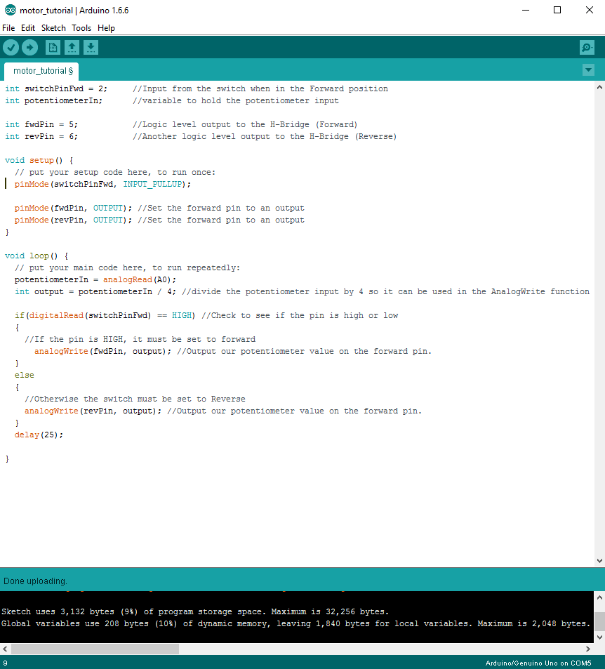
Now that all of the code has been written it can be uploaded to your Arduino! Click “Upload” button in the top left corner of the Arduino IDE and it should upload without any issues. Plug the motor power supply in so the motor has power and after a few seconds try adjusting the potentiometer to adjust the motor speed. When changing directions, ensure the motor is stopped as it is not a good idea to reverse the polarity of a motor while running. Going forward, code could be added to this to prevent the user from changing direction unless the throttle is at 0.
[info]Have A Question?
If you have any questions, or need further clarification please post in the comments section below; this way future users of this tutorial can see the questions and answers!
[/info]
dwolver
thanks
marios papageorgiou
Hello and thanks for sharing this tutorial.
i do have a question however.
i am using arduino mega 2560 and changed my code to fit the switch pin accordingly. switch pin forward = 2 changed to switch pin = 22 my wiering changed as well.
why is it that when i press the pushbutton or the switch, the motor does not change direction?
Ed
Is it possible to short-circuit with this setup? and do you carry brushless waterproof motors I can use with this set up, or would your brushless fans work long term underwater?
jay ring
is it possible to program an arduino uno board to control dc motors from the keyboard of a computer? For example if I press the left arrow button can the board be programmed to turn the motor?
mahadi
is there a problem if i add a powerful motor here ?
Carlos
analogWrite doesn’t work on pin 22. That function only works on digital pins that have the ~ symbol near the pin number.
You can see here:
https://www.arduino.cc/reference/en/language/functions/analog-io/analogwrite/
CJ
Is it possible to use a humidity sensor instead of a switch to control the motor direction? For example, if humidity is a certain high value or higher it spins one way and if lower it spins the other?
Second, is it possible to stop the motor for specific humidity values?
Here is the sensor:
https://learn.sparkfun.com/tutorials/soil-moisture-sensor-hookup-guide
Yoss
First of all, thank you for this very detailed step-by-step tutorial, I wish all tutorials were made with this quality.
Having said that: I can’t get it to work…
Have checked everything many times, and I am quite sure all components, the wiring and the code are identical to what I see on this page.
But as soon as I upload the sketch, the motor starts whirring, even before the battery has been attached (apparently it draws power from the Arduino), the potentiometer has no discernable effect, and the switch only makes the motor go fast or slow, but in the same direction…
Any ideas? Thanks in advance 🙁
Chris @ BCR
If everything is wired & coded exactly the same, i would question whether the H-bridge is faulty
Deardar
//Type between (0-255) in serial monitor to control 1 direction.
//type between (1000-1255) to control opposite direction
int fwdPin = 5; //Logic level output to the H-Bridge (Forward)
int revPin = 6; //Another logic level output to the H-Bridge (Reverse)
int gear = 2;
int speedPwm = 0;
int serialComm;
void setup() {
// put your setup code here, to run once:
Serial.begin(9600);
pinMode(fwdPin, OUTPUT); //Set the forward pin to an output
pinMode(revPin, OUTPUT); //Set the forward pin to an output
}
void loop() {
// put your main code here, to run repeatedly:
if (Serial.available()>0){
serialComm = Serial.parseInt();
Serial.println(“recieved input “);
Serial.println(serialComm);
if(serialComm>999){
gear=0;
speedPwm=serialComm-1000;}
else{
gear=1;
speedPwm=serialComm;}
Serial.println(“setpwm “);
Serial.print(speedPwm);
}
if(gear == 0){//If the gear =0 , it must be set to forward
analogWrite(fwdPin, speedPwm); //Output our potentiometer value on the forward pin.
analogWrite(revPin, 0);
Serial.println(“forward “);
}
else if(gear == 1){//Otherwise the switch must be set to Reverse
analogWrite(revPin, speedPwm); //Output our potentiometer value on the forward pin.
analogWrite(fwdPin, 0);
Serial.println(“rev “);
}
delay(25);
}
Zbrozli
What is a program you using for this project?
I using Tinkercad circuits, but i don’t have same components like you.
William @ BC Robotics
We use Fritzing – great tool!
S.V.S.Charan
hii…
i had a doubt that can is use L293D instead of this H-bridge wt u have used
Hani khaj
Hi. Can I use a higher voltage battery? I just don’t know how make for example 20 V DC Motor to 5 or 9. Can a relay do the job?
RobotD
Has anyone tried connecting another motor and battery to the other side of the H-Bridge and written code to control two motors?
Sandy McLennan
Thanks. Been searching for this specifically: sliding SPDT switch as forward/reverse for motor. Will remember to check here for tutorials.
KLaus
Hi,
thanks a lot for the good work. Difference with other tutorials is the step by step instruction which are very helpfull. Worked perfectly for me!
Klaus
Mark
Thanks very much. I used your code for my Fischer Technic car with FlySky RC controller. I had trouble to connect my Velleman H-bridge. But thanks to your tutorial here everything is working (for interested people, my project is on Github: https://github.com/ME-DataStudio/FT-RC-Robot-Arduino/blob/main/README.md)