BC Robotics
Browse categories
- New Additions
- Shop
- On Sale / Clearance
- Popular Categories
- ArduinoArduino is the most popular open source microcontroller platform on the market. These easy to program devices can read sensors, control relays, light up LEDs, and even talk to one another. Their ability to interact with the real world by way of sensors and other electronics makes them ideal for automation such as watering a plant when it is dry, reading the weather, or controlling lights when it gets dark – the possibilities are endless. We carry a variety of Arduino compatible microcontrollers from several manufacturers, each with their own specific strengths and purposes. To further specialize your microcontroller, we carry a large selection of daughter boards (shields) which can add powerful sensors, GPS, or even LCD screens to your project! Just getting started with microcontrollers? We carry a variety of Arduino starter kits to get you reading sensors and blinking lights as easily as quickly as possible!
- BBC micro:bitThe BBC micro:bit is a pocket-sized computer designed for beginners in electronics and coding. The micro:bit makes getting into these often daunting fields as easy as possible. Programming the micro:bit V2 can be done by computer or by their intuitive app available for Android and iOS devices. Code can be designed using a drag and drop interface in the Blocks editor, Javascript, or Python.
- ESP8266 & ESP32The ESP8266 and ESP32 microcontrollers from Espressif are powerful, inexpensive, and feature integrated WiFi connectivity. These are ideal for IoT applications. We offer a variety of different ESP8266 and ESP32 modules for different skill levels.
- FeatherFeather is a flexible and powerful family of microcontroller main-boards (Feathers) and daughter-boards (Wings) designed with portability in mind. All Feathers have integrated battery connectors (and most have built in lipo chargers) The Feather form factor is not locked to a specific chipset or programming language. Feathers are available with a variety of chipsets and on-board features. Most Feathers and FeatherWings have example code and libraries written in Arduino C/C++ and CircuitPython.
- Makey MakeyThe Makey Makey kit is a electronics kit designed for beginners. It explores the concepts of creating circuits through everyday items. When plugged into a computer you can use the Makey Makey to make anything into a keyboard or mouse. No programming required! Projects like a Banana Drum Set, Cat Detector, Musical Stairs, and countless others are easier than you think! We carry the Makey Makey Classic Kit – a starter kit for the Makey Makey – along with extra alligator clips, copper conductive tape, and replacement cables.
- Raspberry PiThe Raspberry Pi was first introduced in early 2012 as a simple, low cost, computer fit onto a circuit board roughly the size of a credit card. The idea was to use this low cost computer to promote teaching of computer science in schools but it has grown to be so much more! Since its release, well over 30 million of these little computers have been sold. We have carried the Raspberry Pi in Canada since it first became available and have watched as the Pi has morphed into a complete development platform with powerful single-board computers, cameras, touchscreens, and other accessories. Its multitude of inputs and outputs for electronics and computer peripherals and its impressive computing power mean it can be used to make just about anything you can imagine. The newest and most powerful version, the Raspberry Pi 4, is now available!
- Popular Brands
- AdafruitAdafruit was founded in 2005 by MIT engineer, Limor “Ladyada” Fried. Her goal was to create the best place online for learning electronics and making the best designed products for makers of all ages and skill levels. In the last 10 years, Adafruit has grown to over 100+ employees in the heart of NYC with a 50,000+ sq ft. factory.
- ArduinoArduino is an ever growing platform used by some of the most popular microcontrollers out there. For many of us, this is where it all started – the Arduino was (and still is today) a pioneer when it comes to making programming hardware easy and accessible. We have one of the largest selections of Arduino and Arduino accessories in Canada. These range from basic Arduino Uno, to Cellular and WiFi connected devices perfect for the Internet of Things, and all the accessories needed to get them running!
- Micro:bitMicro:bit Educational Foundation are the manufacturers of the popular BBC micro:bit; a pocket-sized computer designed for beginners in electronics and coding. The micro:bit makes getting into these often daunting fields as easy as possible. Programming the micro:bit V2 can be done by computer or by their intuitive app available for Android and iOS devices. Code can be designed using a drag and drop interface in the Blocks editor, Javascript, or Python.
- BC RoboticsIn addition to stocking 2000+ unique items, we also manufacture our own accessories right here at BC Robotics. In 2014 we began developing our own widgets and add-ons for Arduino, Raspberry Pi, and general prototyping. This has now grown to over 80 different SKUs. Our boards are assembled in-house with top quality components. Many feature detailed tutorials or project guides to get you up and running as quickly as possible!
- Raspberry Pi
- SparkFunSince 2003, SparkFun has been helping turn ideas into reality – whether you’re creating a smart weather station, exploring the frontier of machine learning, building a robot for school or prototyping your first (or tenth) product. No matter your vision or skill level, our open source components, resources and online tutorials are designed to broaden access to innovative technology and make the road to a finished project shorter. We’re here to help you start something.
- Frequently Asked Questions
- My Account
- Wishlist
- Cart
Free Shipping - US & Canada @ $150 CAD
Getting Started With BC Robotics Relay Breakouts
PRODUCT TUTORIAL
- Chris @ BCR
- April 21, 2021
- 4:00 pm
- 6 Comments
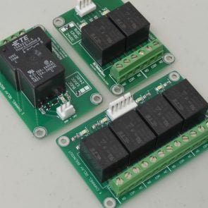
Our Relay Breakout boards are designed to allow microcontrollers (like the Arduino), single board computers (like the Raspberry Pi), and other low power / low current signals to switch high current / high power loads. Relays are one of the easiest ways to control a high current / high voltage load, but a relay cannot simply be connected to a microcontroller, they require several additional components to function correctly and protect the microcontroller from damage. Our breakout boards handle all of this extra circuitry in a compact, easy to use, module.
The boards are offered in a variety of coil voltages (the voltage used to power the relay) and have a wide input voltage for the relay trigger (the low power signal that controls the relay). On the relay contact side, each relay has the common, normally open, and normally closed pin broken out to a convenient 5.0mm pitch screw terminal. If this all sounds over your head, don’t worry, we will be going into this in great detail!
A Few Considerations:
When it comes to choosing relay breakout boards there are a few things to consider:
- What you are controlling (The voltage and current you want to switch on and off using the relay)
- What power you have available (To power the relay coils)
- What is the voltage of the signal you want to trigger the relay with
Safety Note:
The boards are designed to handle higher voltages, but we do not recommend doing so for anyone unfamiliar with the dangers of high voltage. If you are inexperienced or unsure about how to use this product safely we recommend looking at the IoT Power Relay, which has all of its high voltage circuitry fully enclosed.
How It Works
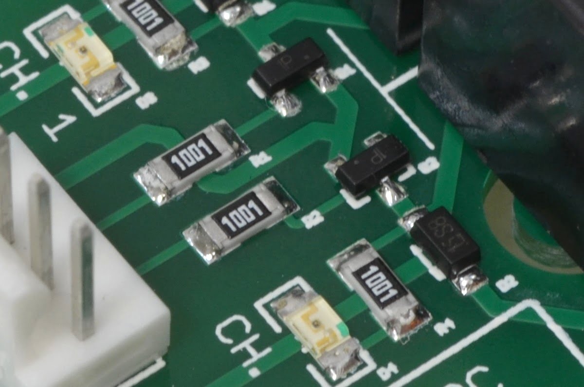
Relays can be thought of as big electronically controlled switches. Being able to control them with a microcontroller or single board computer is one of the key elements in basic automation – but it isn’t as simple as just connecting a relay to your Arduino. Powering a relay requires a lot more current than can be provided by a simple digital output from a microcontroller or single board computer. Also, when the relay coil is de-energized, the reverse voltage spike is particularly harmful to sensitive electronics! So, additional circuitry is required!
Our relay breakouts take this driver circuit and package it neatly on a single circuit board so all you need to do is plug everything in – no need to worry about transistors, diodes, or any of that! Just connect your digital outputs from your controller to the numbered inputs on the breakout along with power for the relay coil(s) and you are good to go!
The Parts Needed

This tutorial will be requiring a few common parts:
1 x any BC Robotics Relay Breakout Board
1 x Arduino, Raspberry Pi, or other control signal source
Controlling The Relays
There is a separate driver circuit for each relay on the board – meaning they can all be individually switched on and off. All of our relay boards can be used with as low as 3.3VDC signals, and right up to the relay coil voltage.
- 5V Relay Breakouts will activate with 3.3 – 5VDC logic signals.
- 12V Relay Breakouts will activate with 3.3 – 12VDC logic signals.
- 24V Relay Breakouts will activate with 3.3. – 24VDC logic signals.
When each trigger wire on the relay breakout has 3.3V or greater applied, a transistor triggers that relay coil, in turn, making the relay switch states. We can connect a digital pin from an Arduino, Raspberry Pi, or any other compatible signal source to each of the trigger pins.
Connecting To The Relay(s) - Power & Control
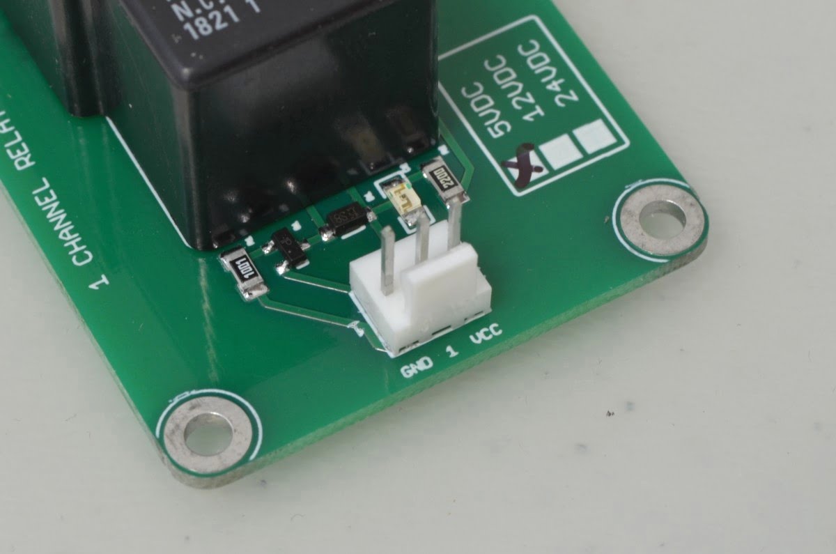
Power and control signals are connected through the small Molex KK connector on the board. Each pin on this connector is labeled; VCC will be equal to the relay coil voltage (so on a 5V relay breakout, 5VDC. etc.). Ground will connect to your common ground. Each relay (if more than one on the board) will have a numbered input corresponding to the relay’s number on the board.
During the prototyping stage you may just want to stick to typical prototyping jumper wires. Beyond prototyping, we recommend switching to a cable using the proper Molex KK series connector.
- 1 Channel Relay Breakouts use a 3 Pin Housing
- 2 Channel Relay Breakouts use a 4 Pin Housing
- 4 Channel Relay Breakouts use a 6 Pin Housing
Housings and Crimp Pins are available here: Molex KK Series . We also have pre-built cables available for each version as well:
- 1 Channel Relay Breakouts use a 3 Pin Cable
- 2 Channel Relay Breakouts use a 4 Pin Cable
- 4 Channel Relay Breakouts use a 6 Pin Cable
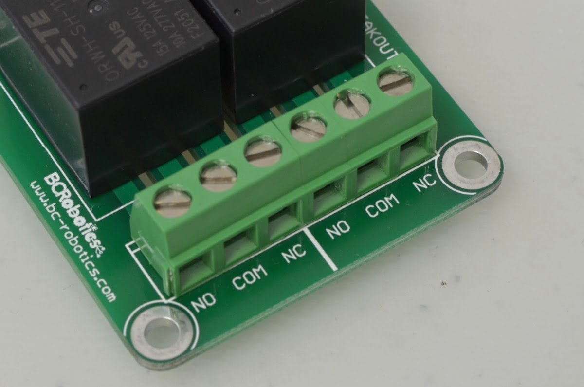
Connecting To The Relay(s) - Contacts
On the Opposite side of the board we have large screw terminals for the relay contacts. The specific relays we use in our Relay Breakout boards are a SPDT contact configuration (Single Pole, Double Throw) meaning they have three contact pins: Normally Closed (NC), Normally Open (NO), and Common (COM). The common pin that is connected to one of the other two contact pins depending on the relay’s state.
When the relay is not powered, it is in its “Normal” state. In the normal state the Normally Closed “NC” pin is connected to the Common pin “COM”. Normally Open “NO” is left open (not connected to anything). Powering the relay coil will change the relay state, meaning the “COM” pin is now connected to “NO” and the “NC” pin is no longer connected to anything. Removing power from the relay coil, the relay reverts back to its normal state once again.
Depending on your application, connect your high current wires to the correct contacts on this side of the board.
Arduino Example:
In this example we will connect a 2 Channel 5V Relay Breakout to an Arduino and show the simplest way to switch it on and off using a microcontroller. Start by wiring the Relay Breakout as shown. For a 1 Channel Relay Breakout, a single digital pin can be used; for a 4 Channel Relay Breakout, 4 digital pins are needed.

- Red: Arduino “5V” Pin to Breakout Board “VCC” Pin
- Black: Arduino “GND” Pin to Breakout Board “GND” Pin
- Yellow: Arduino Digital I/O Pin 2 to Breakout Board “1” Pin
- Green: Arduino Digital I/O Pin 3 to Breakout Board “2” Pin
Now that everything is wired up, we will write the most basic code we can. It will identify what pins the relays are connected to, configure those pins as outputs, and then run a basic loop that switches them on and off one at a time. As before, if you need more or less digital pins, just adjust as needed.
					int relayPin1 = 2; //This is the Arduino Pin that will control Relay #1
int relayPin2 = 3; //This is the Arduino Pin that will control Relay #2

void setup() {
    // put your setup code here, to run once:
    pinMode(relayPin1, OUTPUT); //Configure Arduino Pin 2 as an Output for Relay 1
    pinMode(relayPin2, OUTPUT); //Configure Arduino Pin 3 as an Output for Relay 2

}

void loop() {
    // put your main code here, to run repeatedly:
    digitalWrite(relayPin1, HIGH); //Switch Relay #1 ON
    delay(1000); //Wait 1 Second

    digitalWrite(relayPin1, LOW); //Switch Relay #1 OFF
    delay(1000); //Wait 1 Second

    digitalWrite(relayPin2, HIGH); //Switch Relay #2 ON
    delay(1000); //Wait 1 Second

    digitalWrite(relayPin2, LOW); //Switch Relay #2 OFF
    delay(1000); //Wait 1 Second
}
If we were to upload this code to the Arduino it will turn Relay #1 on for 1 second and then switch it off for 1 second, do the same for Relay 2, and continue through this loop forever. Going forward, this could be further adapted by connecting sensors or other inputs to the Arduino. These inputs could then be used to make decisions about when / how long to turn relays On/Off, forming a basic automation system.
Raspberry Pi Example:
In this example we will connect a 1 Channel 5V Relay Breakout to a Raspberry Pi and show the simplest way to switch it on and off. Start by wiring the Relay Breakout as shown. For a 2 Channel Relay Breakout, two GPIO pins are needed; for a 4 Channel Relay Breakout, four GPIO pins are needed. In this case we are connecting our single relay to GPIO17 (BCM numbering). To figure out what pints are available on the Pi for additional relays, here is a complete pinout of the Raspberry Pi GPIO header.
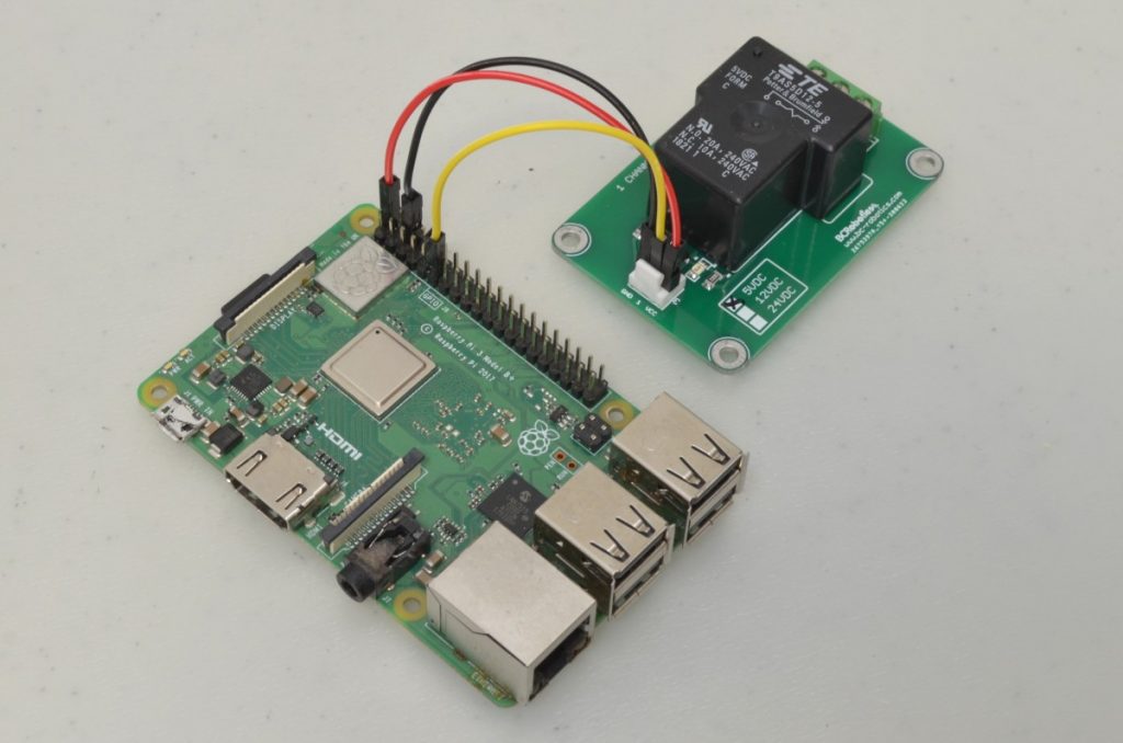
- Red: Raspberry Pi “5V” Pin to Breakout Board “VCC” Pin
- Black: Raspberry Pi “GND” Pin to Breakout Board “GND” Pin
- Yellow: Raspberry Pi GPIO 17 to Breakout Board “1” Pin
Now that everything is wired up, we will write the most basic Python code we can. It will import the needed software libraries, configure the Raspberry Pi GPIO pin numbering scheme, configure the correct pin as an output, and then run a basic loop that switches the relay on and off. As before, if you need more GPIO pins, just adjust as needed.
					import time
import RPi.GPIO as GPIO

GPIO.setmode(GPIO.BCM) #Broadcom pin-numbering scheme
GPIO.setup(17, GPIO.OUT) #set Relay 1 output

interval = 1 # How long we want to wait while the relay is on(seconds)

GPIO.output(17, GPIO.HIGH) #turn relay 1 on
time.sleep(interval)
GPIO.output(17, GPIO.LOW) #turn relay 1 off
If we were to run this code by pressing “F5” it will turn Relay #1 on for 1 second and then switch it off. Going forwards, the amount of time the relay stays on for could be adjusted and this code could be run at a specific time or at a specific intervals of time using our Cron Tutorial, resulting in a basic scheduled on/off switch.
6 thoughts on “Getting Started With BC Robotics Relay Breakouts”
d3howard
If the coils on both relays are activated at the same time, how much current (from the 5V power supply) does the module draw?
Chris @ BCR
Total draw with both relays active is approx. 350mA
Tommy
Since the relay coils are powered via an external supply, how much current does the transistor draw from each microcontroller pin?
William @ BC Robotics
Each line will draw approx. 2mA
martin c
Are the NC NO Com of say a 2 relay module not connected to each other in anyway and are the contacts “dry”? Tks
Chris @ BCR
Hi Martin – each of the contacts are individually isolated so COM(1) is isolated from COM(2) etc. These would be considered Dry Contact boards as coil power is provided from the control side of the circuit (white Molex connector) Let us know if you have any additional questions!