BC Robotics
Browse categories
- New Additions
- Shop
- On Sale / Clearance
- Popular Categories
- ArduinoArduino is the most popular open source microcontroller platform on the market. These easy to program devices can read sensors, control relays, light up LEDs, and even talk to one another. Their ability to interact with the real world by way of sensors and other electronics makes them ideal for automation such as watering a plant when it is dry, reading the weather, or controlling lights when it gets dark – the possibilities are endless. We carry a variety of Arduino compatible microcontrollers from several manufacturers, each with their own specific strengths and purposes. To further specialize your microcontroller, we carry a large selection of daughter boards (shields) which can add powerful sensors, GPS, or even LCD screens to your project! Just getting started with microcontrollers? We carry a variety of Arduino starter kits to get you reading sensors and blinking lights as easily as quickly as possible!
- BBC micro:bitThe BBC micro:bit is a pocket-sized computer designed for beginners in electronics and coding. The micro:bit makes getting into these often daunting fields as easy as possible. Programming the micro:bit V2 can be done by computer or by their intuitive app available for Android and iOS devices. Code can be designed using a drag and drop interface in the Blocks editor, Javascript, or Python.
- ESP8266 & ESP32The ESP8266 and ESP32 microcontrollers from Espressif are powerful, inexpensive, and feature integrated WiFi connectivity. These are ideal for IoT applications. We offer a variety of different ESP8266 and ESP32 modules for different skill levels.
- FeatherFeather is a flexible and powerful family of microcontroller main-boards (Feathers) and daughter-boards (Wings) designed with portability in mind. All Feathers have integrated battery connectors (and most have built in lipo chargers) The Feather form factor is not locked to a specific chipset or programming language. Feathers are available with a variety of chipsets and on-board features. Most Feathers and FeatherWings have example code and libraries written in Arduino C/C++ and CircuitPython.
- Makey MakeyThe Makey Makey kit is a electronics kit designed for beginners. It explores the concepts of creating circuits through everyday items. When plugged into a computer you can use the Makey Makey to make anything into a keyboard or mouse. No programming required! Projects like a Banana Drum Set, Cat Detector, Musical Stairs, and countless others are easier than you think! We carry the Makey Makey Classic Kit – a starter kit for the Makey Makey – along with extra alligator clips, copper conductive tape, and replacement cables.
- Raspberry PiThe Raspberry Pi was first introduced in early 2012 as a simple, low cost, computer fit onto a circuit board roughly the size of a credit card. The idea was to use this low cost computer to promote teaching of computer science in schools but it has grown to be so much more! Since its release, well over 30 million of these little computers have been sold. We have carried the Raspberry Pi in Canada since it first became available and have watched as the Pi has morphed into a complete development platform with powerful single-board computers, cameras, touchscreens, and other accessories. Its multitude of inputs and outputs for electronics and computer peripherals and its impressive computing power mean it can be used to make just about anything you can imagine. The newest and most powerful version, the Raspberry Pi 4, is now available!
- Popular Brands
- AdafruitAdafruit was founded in 2005 by MIT engineer, Limor “Ladyada” Fried. Her goal was to create the best place online for learning electronics and making the best designed products for makers of all ages and skill levels. In the last 10 years, Adafruit has grown to over 100+ employees in the heart of NYC with a 50,000+ sq ft. factory.
- ArduinoArduino is an ever growing platform used by some of the most popular microcontrollers out there. For many of us, this is where it all started – the Arduino was (and still is today) a pioneer when it comes to making programming hardware easy and accessible. We have one of the largest selections of Arduino and Arduino accessories in Canada. These range from basic Arduino Uno, to Cellular and WiFi connected devices perfect for the Internet of Things, and all the accessories needed to get them running!
- Micro:bitMicro:bit Educational Foundation are the manufacturers of the popular BBC micro:bit; a pocket-sized computer designed for beginners in electronics and coding. The micro:bit makes getting into these often daunting fields as easy as possible. Programming the micro:bit V2 can be done by computer or by their intuitive app available for Android and iOS devices. Code can be designed using a drag and drop interface in the Blocks editor, Javascript, or Python.
- BC RoboticsIn addition to stocking 2000+ unique items, we also manufacture our own accessories right here at BC Robotics. In 2014 we began developing our own widgets and add-ons for Arduino, Raspberry Pi, and general prototyping. This has now grown to over 80 different SKUs. Our boards are assembled in-house with top quality components. Many feature detailed tutorials or project guides to get you up and running as quickly as possible!
- Raspberry Pi
- SparkFunSince 2003, SparkFun has been helping turn ideas into reality – whether you’re creating a smart weather station, exploring the frontier of machine learning, building a robot for school or prototyping your first (or tenth) product. No matter your vision or skill level, our open source components, resources and online tutorials are designed to broaden access to innovative technology and make the road to a finished project shorter. We’re here to help you start something.
- Frequently Asked Questions
- My Account
- Wishlist
- Cart
Free Shipping - US & Canada @ $150 CAD
Getting Started With Power HATs
PRODUCT TUTORIAL
- Chris @ BCR
- May 7, 2021
- 1:58 pm
- 4 Comments
Our Raspberry Pi Power HATs are a series of Raspberry Pi Add-on boards dedicated to providing the Raspberry Pi with reliable 5V power at 3A from input sources ranging from 7-16VDC. This enables the Pi to run in Automotive, Marine, and other systems in the 7-16VDC range without the need for a complicated AC inverter or external DC/DC converter. Just connect your power source into the HAT and that’s it!
About The Boards:
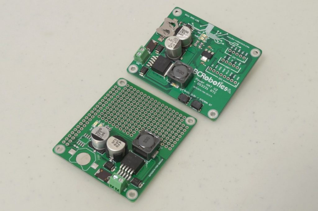
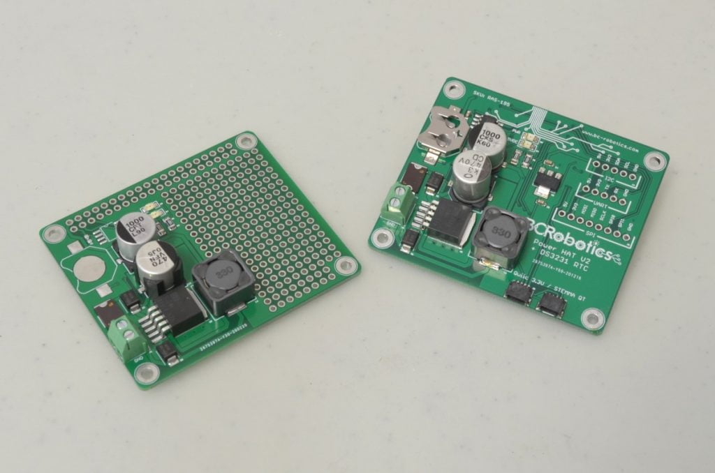
We make three versions of the Raspberry Pi Power HAT and offer each version in an assembled or bare bones configuration. The PowerHAT is available as a plain power input HAT, a Power input HAT with DS3231 Real Time Clock, or a Power Input HAT with a 40mm integrated cooling fan. All of these boards share the same robust 5V 3A power regulator and are comfortable powering the Pi under high load all day long. Our boards are compatible with all versions of the Pi from the original A+ and B+ onwards.
Step 1 - A Quick Overview
Since all of these boards share the same power regulator circuit, we are going to look at connecting power first and then split off and go over the three versions separately to look at specifics of each board.
For any unassembled versions (RAS-111, RAS-140, or RAS-165) a Raspberry Pi GPIO header will need to be soldered to the board. We will go into this in depth.
For all assembled versions (RAS-188, RAS-195, or RAS-196) – skip to Step 4.
11.1%
Step 2 – Soldering The Header
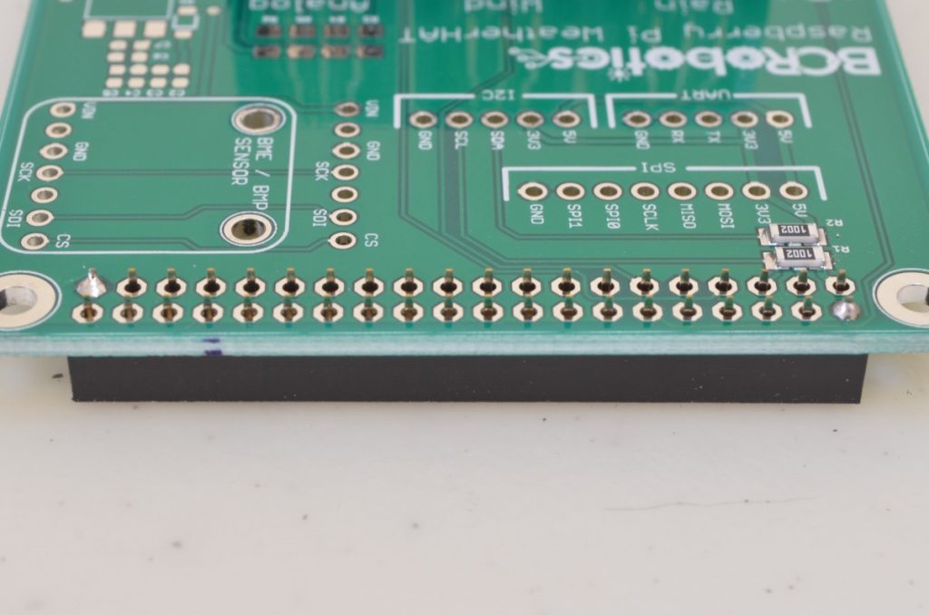
First we need to solder the header that allows this board to plug into the Raspberry Pi. We recommend using this header, but any compatible Raspberry PI GPIO header will work. If you haven’t soldered before, or want a quick refresher course, have a look at this awesome comic: Soldering Is Easy! Start by Tacking two opposite corners of the connector in place and checking the connector alignment. We do this to ensure the connector is sitting correctly before soldering all 40 pins; once these have all been soldered, it is very difficult to adjust the alignment.
22.2%
Step 3 – Soldering The Header (continued)
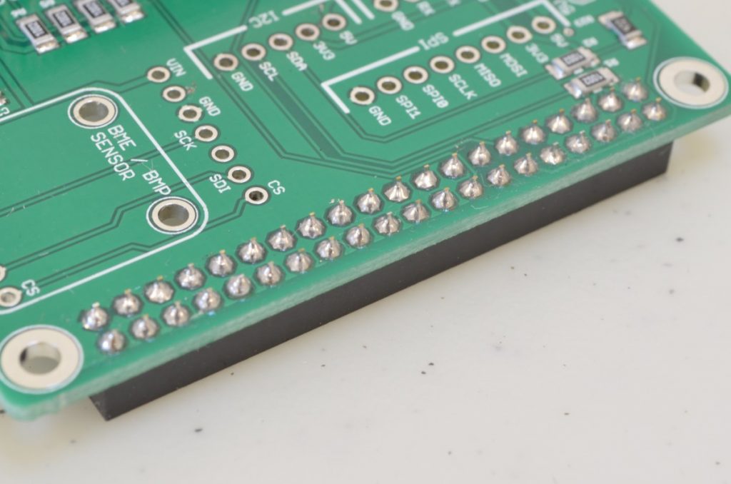
Once the connector is aligned to the board, and you are happy with the alignment, solder the remaining pins. It should look something like the header in the attached photo when you are finished!
33.3%
Step 4 – Connecting To The Pi
Connecting the Power HAT to a Raspberry Pi is done in the same manner as any other Raspberry Pi HAT. The 40 Pin header is designed to align with the Raspberry Pi header, and will occupy all pins. Ensure the Pi is aligned correctly and all pins of the 40 Pin GPIO are occupied.
44.4%
Step 5 – HAT Hardware
When using HATs with the Raspberry Pi, we recommend some form of standoff hardware to keep everything firmly connected. In this tutorial, depending on whether you are using an assembled board or a custom header, the height between boards will vary, meaning different hardware will be needed for each.
For all assembled boards we recommend Raspberry Pi HAT Hardware – 1/2″. It is a touch taller than needed, but the nylon standoffs included in the kit can be filed down.
If you are using a custom header, you will need to look up the between board height of the header you are using and find an appropriate set of standoffs.

55.6%
Step 6 - A Quick Overview

Before we power anything up, it is always a good idea to go through and make sure there are no issues with the work that has been done. Make sure all the solder joints are clean, with no un-intended bridging.
Note: If using the Raspberry Pi 3B+ or newer be sure to check the POE header (located near the USB ports) is not contacting anything on the bottom of your Power HAT.
66.7%
Step 7 – Sourcing Power
Caution
Before continuing: A thorough understanding of your power source is required to safely use this device. If you do not have a complete understanding of your power source, the power it is available to provide, or how to connect to it safely, please consult a professional.
Unlike using a regular Pi Power Supply drawing power from a regular AC power outlet, additional care needs to be taken when sourcing power from a DC / unconventional source. The power source needs to have sufficient current available to power everything being connected to it.
Power Requirements:
- Voltage: 7-16VDC
- Available Power: 15W (minimum)
77.8%
Step 8 – Connecting Power

All Power HATs have a fused input on the board to prevent issues if a short circuit occurred on the board itself. This does not protect the wire running power to the board. Fuse your power wire at the source end of the wire. Inline fuses are an easy way to do this!
Connecting Your Power:
Power Down / disconnect / isolate your power source
Remove the fuse from your fuse holder
Connect your fused wire from the power source to the “VCC” screw terminal on the Power HAT
Connect your ground wire from the power source’s common ground to the “GND” screw terminal on the Power HAT
88.9%
Step 9 – Double Check Your Work – Again!
Now that everything is connected (aside from the fuse completing the circuit) we can, once again, go over our work. Check the screw terminals are tight, use a multimeter to ensure there are no shorts between VCC and GND. Ensure all connections / wire splices are adequately protected. Once everything has been thoroughly checked, power up / reconnect your power source. Check for any issues. The fuse can now be installed to send power to the PowerHAT. Two LEDs will immediately light up indicating power to the board and power to the Pi are being provided. If one or both of these LEDs are not lit or seem very dim, pull the fuse immediately, check everything thoroughly, and seek additional assistance.
Please Note: There is no On/Off switch on these boards – the Pi will boot as soon as power is provided.
100%
Board Specific Details
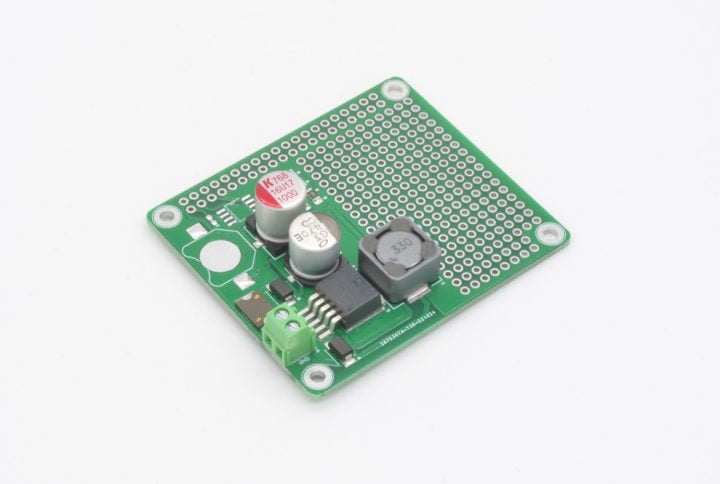
RAS-140 - Raspberry Pi Power HAT
The Raspberry Pi Power HAT is a basic version of the Power HAT series of boards. It features the standard Power HAT circuit along with a small prototyping area. The through plated holes in the prototyping area do not have any interconnection and can be used just like any normal perfboard.
GPIO Header Installed: None
GPIO Pins Used: None
Compatible With:

RAS-196 - Raspberry Pi Power HAT – Assembled
The Raspberry Pi Power HAT – Assembled is a basic version of our Power HAT board in a fully assembled configuration – no soldering required. It features the standard Power HAT circuit and two SparkFun Qwiic / Adafruit STEMMA QT connections.
For further expandability the board also breaks out the UART, I2C, and SPI busses to 0.1” / 2.54mm pitch headers. Additionally, we have included a 3.3V Regulator to ensure sufficient power for all your external sensor needs.
GPIO Header Installed: Standard SMD Header
GPIO Pins Used: None
Compatible With:
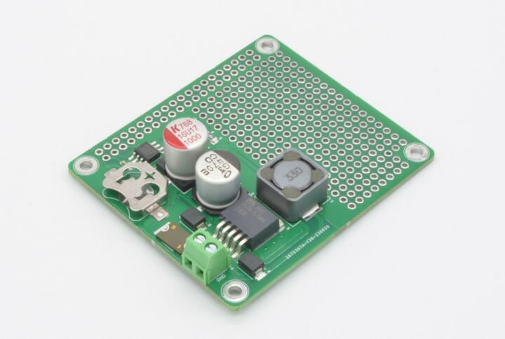
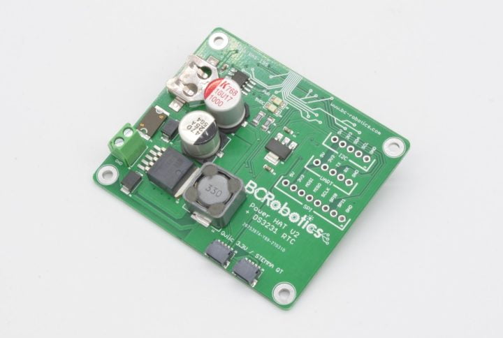
RAS-111 - Raspberry Pi Power RTC HAT
The Raspberry Pi Power RTC HAT is a combination power / real time clock board. It features the standard Power HAT circuit, a DS3231 temperature compensated real time clock (RTC), coin cell slot for RTC battery backup, and small prototyping area.
The RTC is available at i2c address 0x68 and can be set up with ease on most current Raspberry Pi distributions. Adafruit has a great tutorial on how to set this up!
GPIO Header Installed: None
GPIO Pins Used: i2c Address 0x68
Compatible With:
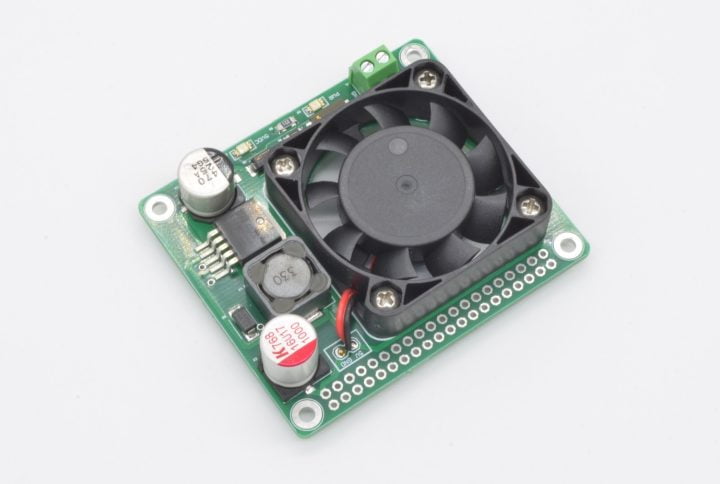
RAS-165 – Raspberry Pi Power / Fan HAT
The Raspberry Pi Power / Fan HAT is a combination of two of our most popular Raspberry Pi add-ons. This board is based on the same beefy 3A 5V DC/DC converter found on our Power and Power RTC HAT and features the same 40mm fan used on our Fan HAT. Combined, this will comfortably power your Pi from 7-16V while keeping it cool under heavy load.
GPIO Header Installed: None
GPIO Pins Used: None
Compatible With:
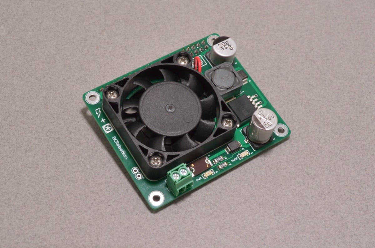
RAS-188 – Raspberry Pi Power / Fan HAT – Assembled
The Raspberry Pi Power / Fan HAT is a combination of two of our most popular Raspberry Pi add-ons in a fully assembled with no soldering required. This board is based on the same beefy 3A 5V DC/DC converter found on our Power and Power RTC HAT and features the same 40mm fan used on our Fan HAT. Combined, this will comfortably power your Pi from 7-16V while keeping it cool under heavy load.
GPIO Header Installed: ACC-055
GPIO Pins Used: None
Compatible With:
RAS-195 - Raspberry Pi Power RTC HAT – Assembled
The Raspberry Pi Power HAT – Assembled is a combination power / real time clock board. It features the standard Power HAT circuit, a DS3231 temperature compensated real time clock (RTC), coin cell slot for RTC battery backup, and two SparkFun Qwiic / Adafruit STEMMA QT connections.
The RTC is available at i2c address 0x68 and can be set up with ease on most current Raspberry Pi distributions. Adafruit has a great tutorial on how to set this up!
For further expandability, the board also breaks out the UART, I2C, and SPI busses to 0.1” / 2.54mm pitch headers. Additionally, we have included a 3.3V Regulator to ensure sufficient power for all your external sensor needs.
GPIO Header Installed: Standard SMD Header
GPIO Pins Used: i2c Address 0x68
Compatible With:
Power Fan HAT - Soft Shutdown

Both the assembled and non-assembled version of the Raspberry Pi Power / FAN HAT have an additional header that allows for the use of a momentary pushbutton for soft shutdown. To enable this feature, enter the following text in your /boot/config.txt file:
dtoverlay=gpio-shutdown enabled
Now simply connect a momentary button to these two pins. Pressing the button will trigger a soft shutdown of the Pi. Press the button again, and the Pi will boot right up.
Raspberry Pi 4:
At this time, the Pi 4 is only capable of shutdown and will not restart without modifying the bootloader.
4 thoughts on “Getting Started With Power HATs”
Grant Schemmel
Hi, when I received my RAS-165 power hat, there were no instructions on how to hook up a momentary switch start shutdown or power up. Does this use the two holes marked J2?
Chris @ BCR
Hey Grant,
Looks like the link to the tutorial disappeared from the product page. We have a note right at the end regarding the soft shutdown: There were some updates recently that may have caused issues with the tutorial as well – Let us know if you have any further questions!
Brian Cook
with the
RAS-188 – Raspberry Pi Power / Fan HAT
is it stackable, or do the header pins terminate.
William @ BC Robotics
Hi Brian,
RAS-188 pins are dead-ended, so it is not possible to stack – but RAS-165 can use any stackable header so it is possible to stack that one.