BC Robotics
Browse categories
- New Additions
- Shop
- On Sale / Clearance
- Popular Categories
- ArduinoArduino is the most popular open source microcontroller platform on the market. These easy to program devices can read sensors, control relays, light up LEDs, and even talk to one another. Their ability to interact with the real world by way of sensors and other electronics makes them ideal for automation such as watering a plant when it is dry, reading the weather, or controlling lights when it gets dark – the possibilities are endless. We carry a variety of Arduino compatible microcontrollers from several manufacturers, each with their own specific strengths and purposes. To further specialize your microcontroller, we carry a large selection of daughter boards (shields) which can add powerful sensors, GPS, or even LCD screens to your project! Just getting started with microcontrollers? We carry a variety of Arduino starter kits to get you reading sensors and blinking lights as easily as quickly as possible!
- BBC micro:bitThe BBC micro:bit is a pocket-sized computer designed for beginners in electronics and coding. The micro:bit makes getting into these often daunting fields as easy as possible. Programming the micro:bit V2 can be done by computer or by their intuitive app available for Android and iOS devices. Code can be designed using a drag and drop interface in the Blocks editor, Javascript, or Python.
- ESP8266 & ESP32The ESP8266 and ESP32 microcontrollers from Espressif are powerful, inexpensive, and feature integrated WiFi connectivity. These are ideal for IoT applications. We offer a variety of different ESP8266 and ESP32 modules for different skill levels.
- FeatherFeather is a flexible and powerful family of microcontroller main-boards (Feathers) and daughter-boards (Wings) designed with portability in mind. All Feathers have integrated battery connectors (and most have built in lipo chargers) The Feather form factor is not locked to a specific chipset or programming language. Feathers are available with a variety of chipsets and on-board features. Most Feathers and FeatherWings have example code and libraries written in Arduino C/C++ and CircuitPython.
- Makey MakeyThe Makey Makey kit is a electronics kit designed for beginners. It explores the concepts of creating circuits through everyday items. When plugged into a computer you can use the Makey Makey to make anything into a keyboard or mouse. No programming required! Projects like a Banana Drum Set, Cat Detector, Musical Stairs, and countless others are easier than you think! We carry the Makey Makey Classic Kit – a starter kit for the Makey Makey – along with extra alligator clips, copper conductive tape, and replacement cables.
- Raspberry PiThe Raspberry Pi was first introduced in early 2012 as a simple, low cost, computer fit onto a circuit board roughly the size of a credit card. The idea was to use this low cost computer to promote teaching of computer science in schools but it has grown to be so much more! Since its release, well over 30 million of these little computers have been sold. We have carried the Raspberry Pi in Canada since it first became available and have watched as the Pi has morphed into a complete development platform with powerful single-board computers, cameras, touchscreens, and other accessories. Its multitude of inputs and outputs for electronics and computer peripherals and its impressive computing power mean it can be used to make just about anything you can imagine. The newest and most powerful version, the Raspberry Pi 4, is now available!
- Popular Brands
- AdafruitAdafruit was founded in 2005 by MIT engineer, Limor “Ladyada” Fried. Her goal was to create the best place online for learning electronics and making the best designed products for makers of all ages and skill levels. In the last 10 years, Adafruit has grown to over 100+ employees in the heart of NYC with a 50,000+ sq ft. factory.
- ArduinoArduino is an ever growing platform used by some of the most popular microcontrollers out there. For many of us, this is where it all started – the Arduino was (and still is today) a pioneer when it comes to making programming hardware easy and accessible. We have one of the largest selections of Arduino and Arduino accessories in Canada. These range from basic Arduino Uno, to Cellular and WiFi connected devices perfect for the Internet of Things, and all the accessories needed to get them running!
- Micro:bitMicro:bit Educational Foundation are the manufacturers of the popular BBC micro:bit; a pocket-sized computer designed for beginners in electronics and coding. The micro:bit makes getting into these often daunting fields as easy as possible. Programming the micro:bit V2 can be done by computer or by their intuitive app available for Android and iOS devices. Code can be designed using a drag and drop interface in the Blocks editor, Javascript, or Python.
- BC RoboticsIn addition to stocking 2000+ unique items, we also manufacture our own accessories right here at BC Robotics. In 2014 we began developing our own widgets and add-ons for Arduino, Raspberry Pi, and general prototyping. This has now grown to over 80 different SKUs. Our boards are assembled in-house with top quality components. Many feature detailed tutorials or project guides to get you up and running as quickly as possible!
- Raspberry Pi
- SparkFunSince 2003, SparkFun has been helping turn ideas into reality – whether you’re creating a smart weather station, exploring the frontier of machine learning, building a robot for school or prototyping your first (or tenth) product. No matter your vision or skill level, our open source components, resources and online tutorials are designed to broaden access to innovative technology and make the road to a finished project shorter. We’re here to help you start something.
- Frequently Asked Questions
- My Account
- Wishlist
- Cart
Free Shipping - US & Canada @ $150 CAD
Getting Started With The Raspberry Pi Pico Irrigation Board
PRODUCT TUTORIAL
- Chris @ BCR
- March 20, 2023
- 11:45 am
- One Comment
With the release of the Raspberry Pi Pico, a whole host of low cost / low power automation projects are now possible while remaining within the Raspberry Pi ecosystem! This powerful little microcontroller is easy to work with and features MicroPython and Arduino support. To help the Pico reach out and work with the world around it we have created a series of add-on boards that provide power regulation, sensor connections, and additional functionality.
About The Boards:
Our Raspberry Pi Pico Irrigation Board is one of several boards designed to make automation using the Pi Pico as simple as possible! This board combines 5 MOSFET driver circuits for inductive loads, a power regulator circuit, and Qwiic / STEMMA QT connector to provide a quick method of connecting a variety of sensors and breakout boards. The 1591B form factor means it will fit in the popular series of Hammond 1591B enclosures.

The Parts Needed
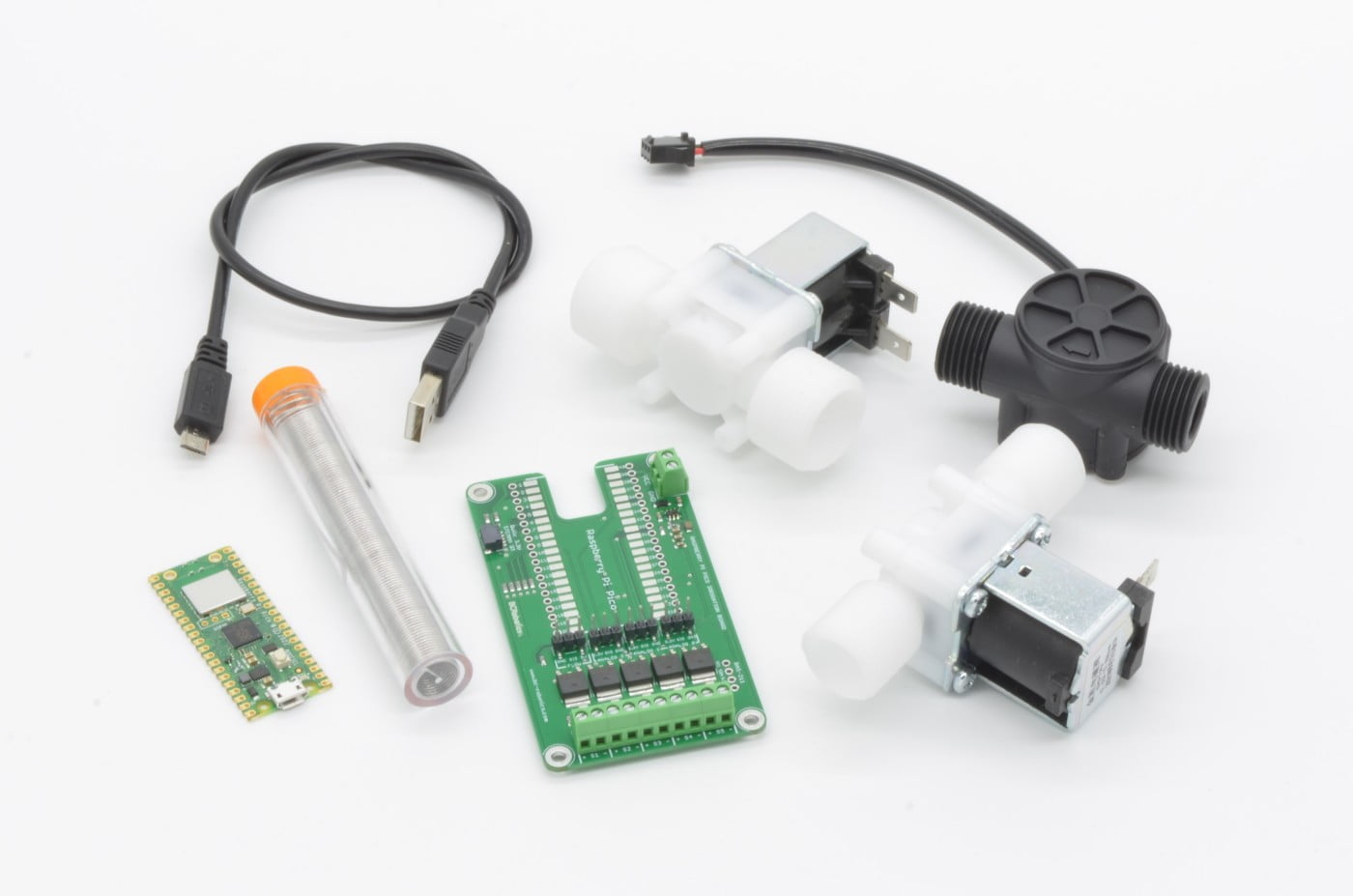
Since this board is mostly assembled, all that is specifically required is a Raspberry Pi Pico. At the time of writing this tutorial, the choice is simply between a Pico or Pico W. Choosing between the two is quite simple – if you need internet or network connectivity, a Pico W is recommended. If you do not, then a plain Pico will work just fine.
1 x Raspberry Pi Pico - or - Raspberry Pi Pico W
1 x USB micro Cable
1 x Raspberry Pi Pico Irrigation Board
Solder + Soldering Iron
9-15VDC Power Source
Optionally:
1 x Hammond 1591B Enclosure
4 x 4/40 x 1/4" Screws
1 x Flow Sensor
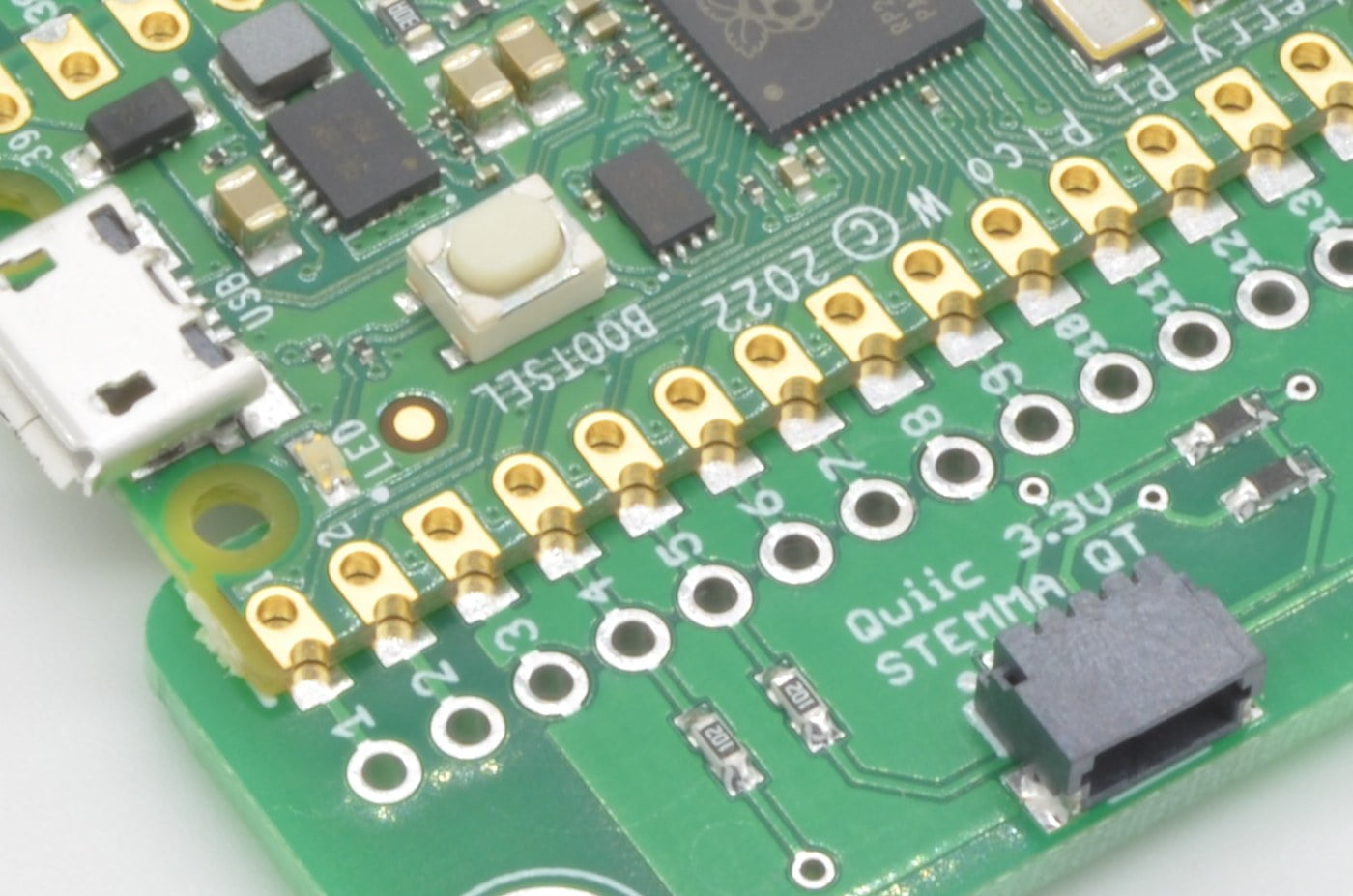
Step 1 - A Quick Overview
There are a few things we will need to solder to the Irrigation Board to get up and running. Starting with the most important part first, we will need to attach the Raspberry Pi Pico W.
Similar to the ESP series of microcontrollers, the Raspberry Pi Pico uses castellated edges on the board, allowing this to be surface mounted to the board below. Don’t be thrown off by the surface mount soldering – this is a very easy method of connecting two boards, well suited to conventional soldering irons and solder. No special SMT soldering equipment / reflow / etc. are required.
⚠ Caution ⚠
We do not recommend using reflow methods to solder the Pico to the Weather Board. The plastics used in through hole connectors tend not to like the temperatures involved and may result in deformed or damaged connectors.
10%
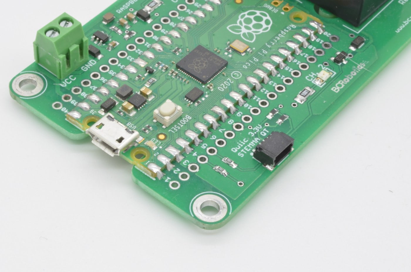
Step 2 - Soldering The Pico (Part 1)

Please Note:
We are going to borrow a few of the soldering photos from the 1591 Relay Board Tutorial (as the process is identical).
In the next few steps we will get the Pico attached to the Pico 1591B Irrigation Board. This is very easy to do, simply line up the board on the outline as shown in the image. We are just going to solder one pin in one corner to ensure everything is lined up as it should.
Don’t solder all the points at once, as adjusting the placement of the board is extremely difficult once several solder pads are filled. This method allows the single point to be reheated and the board moved if adjustment is needed.

We are going to start by soldering pin 1 in the corner. Carefully fill the pad with solder and allow it to flow between the Pico and the Irrigation Board. Your end result should be similar to the pad shown in our example photo.
20%
Step 3 - Soldering The Pico (Part 2)
Once the alignment is good, solder an opposite corner to ensure everything is locked in place. In this case, the opposite pin is 21, close to the vertical headers for the analog inputs (so ignore the relays on this example image!)

If everything is still aligned as it should be, we can now solder all the remaining pads. Your result should be similar to the example image.
After this is complete, inspect your work and ensure there are no bridges between adjacent pads. Once you are satisfied the soldering completed correctly, we can move on to the next step!
30%
Step 4 - Solenoid Wiring

The board can handle up to 5 solenoids, each driven by its own MOSFET based driver circuit. You can use our 1/2″ Solenoid Valve or 3/4″ Solenoid Valve. If you need higher flow, off the shelf commercial 12V solenoids found in the irrigation section of your local hardware store can also be used.
Each circuit has its own snub diode and LED indicator. While we refer to driving solenoids with each circuit, you could directly drive external relays or small pumps as well. Each circuit is capable of driving in excess of 1.5A @12V without getting too hot.
To connect your solenoid, simply run each wire into the screw terminal and clamp it down. For many multi-zone sprinkler systems wired with a commercial controller, power will be provided over a single wire. In this case, connect the power wire to one of the positive terminals, with each ground going to its respective terminal on the board.
40%
Step 5 - Flow Sensor Wiring
We base this tutorial around the YF-S201 Flow Sensor. This is very easy to install, simply plug the senor into the 3 pin header marked “Flow” oriented so the black wire is connected to the pin labeled “GND” and the red wire is connected to the pin labeled “5V”. That’s it!
Note:
The length of cable used with most flow sensors can be quite short, we would recommend using a longer cable with a connector unlikely to conflict with the neighboring Analog Input Headers. Most Dupont or Molex 0.100 / 2.54mm pitch headers will work.

50%
Step 6 – Double Check Your Work!
Before we power anything up, take another good look at the work that has been done. Make sure all solder joints are clean, nothing looks out of the ordinary, and no components were damaged / moved / removed during the soldering process. Once the board has been thoroughly checked, we can move on.
60%
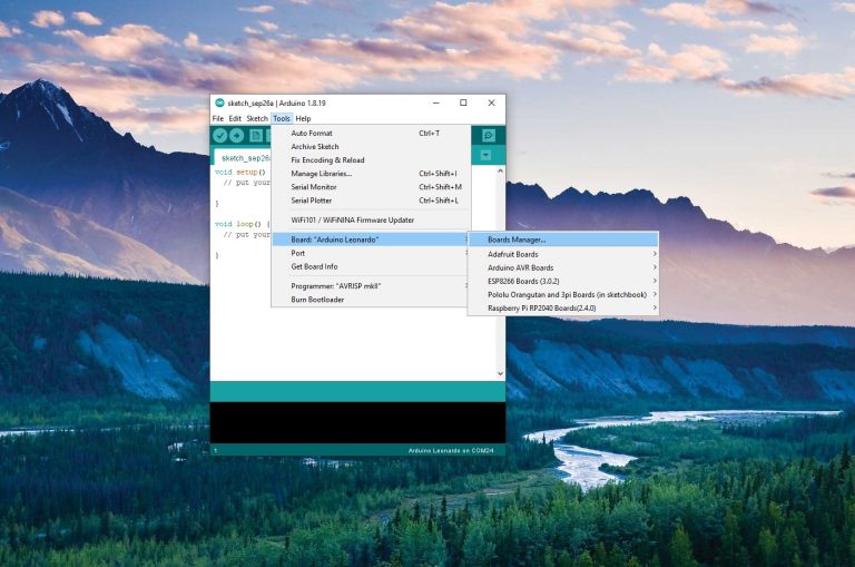
Step 7 - Getting Started With Programming
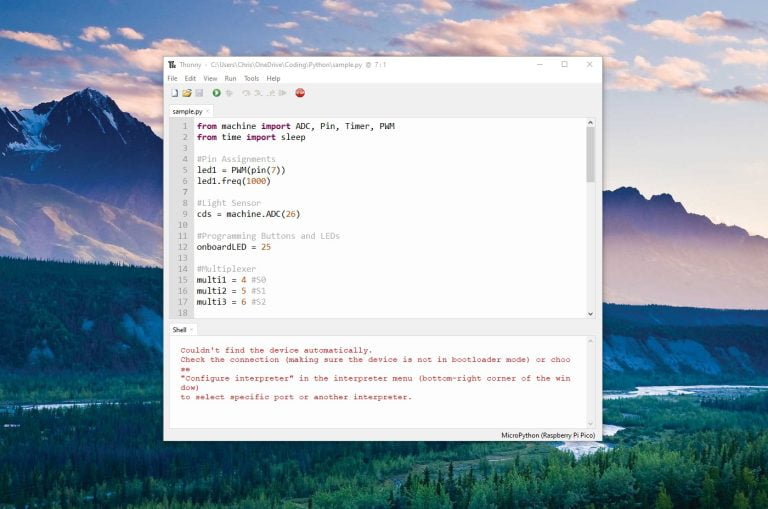
Time to plug it in and get started! The assembled Pico / Relay Board will act just like a regular Pico when plugged in via USB. In this tutorial we are going to look at both MicroPython (Using Thonny) and Arduino (Using the Arduino IDE). You can choose which ever you are more comfortable with!
If this is a brand new Pico, you will need to flash the bootloader. Below we have links to getting a Pico set up with both Arduino and Thonny.
Arduino Setup
MicroPython Setup
Programming the Raspberry Pi Pico with MicroPython
September 28, 2022
3 Comments
Once everything is set up, we can move to the next step.
70%
Step 8 - Starting The Code
					void setup() {
// put your setup code here, to run once:
}
void loop() {
// put your main code here, to run repeatedly:
}
In this quick example code, we are going to write a very simple irrigation program. This program will trigger each solenoid one-by-one and let it run for 5 minutes. During this time, our flow sensor will be monitoring how much water is allowed into the system (we assume this sensor is installed at the inlet, before all of the solenoids).
At the end of each solenoid’s 5 minutes, we will report the water consumed by that “watering zone” by writing it to the Serial monitor. The count will then reset, and the system will move on to the next solenoid.
Since we are looking at two different programming examples, if you are interested in Arduino, we will address that first. If you are more comfortable with Python, skip down to the Python Example.
80%
Arduino Example
We are starting with the BareMinimum Sketch found in the IDE, it should look something like this:
					void setup() {
// put your setup code here, to run once:
}
void loop() {
// put your main code here, to run repeatedly:
}
First we will need to create a array (list) of the pins used by the solenoids. We use an array to store the pin numbers to make the code more organized, efficient, and easy to maintain. By storing the solenoid pin numbers in an array, we can take advantage of loops and other programming constructs to perform operations on multiple solenoids without writing the same code over and over again for each specific solenoid.
					const int solenoidPins[] = {2, 3, 4, 5, 6};

void setup() {
  // put your setup code here, to run once:
}

void loop() {
  // put your main code here, to run repeatedly:
}
To iterate through this array, we also need to know how long the array is. We could very easily just enter “5” as that is the number of items in the array we just set up, but best practice would be to calculate it on first starting the code like this:
					const int solenoidPins[] = {2, 3, 4, 5, 6};
const int numSolenoids = sizeof(solenoidPins) / sizeof(solenoidPins[0]);

void setup() {
  // put your setup code here, to run once:
}

void loop() {
  // put your main code here, to run repeatedly:
}
Next we need to define a few things about the flow sensor. The sensor is connected to GPIO pin 7 and will go LOW each time approx. 2.25mL of water flows by. So we will need to define the IO pin and store the volume of water as a constant. That way we can just count the number of times we get a low signal and multiply by the constant of 2.25mL. We will also need to create a variable to hold the number of detections of the LOW signal as well as the 5 minute run time for the solenoids.
					const int solenoidPins[] = {2, 3, 4, 5, 6};
const int numSolenoids = sizeof(solenoidPins) / sizeof(solenoidPins[0]);

int flowSensorPin = 7; //This is our flow sensor input
volatile unsigned long tickCount = 0; // Store tick count, use 'volatile' as it's modified in interrupt
const unsigned long solenoidRunTime = 5 * 60 * 1000; // 5 minutes in milliseconds
const float tickToVolume = 2.25; // 1 tick = 2.25 mL

void setup() {
  // put your setup code here, to run once:
}

void loop() {
  // put your main code here, to run repeatedly:
}
In the next step, we will fill in our Setup function. In here we will enable our serial port and set up each of the input and output pins.
Since we have an array of pins for the solenoids this will be very short. We are simply going to iterate through the list, and for each one, configure it as an OUTPUT
Since there is only one INPUT pin, no fancy code is required to iterate through them, but we do need to attach an interrupt to the pin. An interrupt is a method of easily checking when the state of a pin changes. We have chosen to use the transition “RISING” meaning we only want to know when it transitions from LOW to HIGH and we ignore everything else.
					const int solenoidPins[] = {2, 3, 4, 5, 6};
const int numSolenoids = sizeof(solenoidPins) / sizeof(solenoidPins[0]);

int flowSensorPin = 7; //This is our flow sensor input
volatile unsigned long tickCount = 0; // Store tick count, use 'volatile' as it's modified in interrupt
const unsigned long solenoidRunTime = 5 * 60 * 1000; // 5 minutes in milliseconds
const float tickToVolume = 2.25; // 1 tick = 2.25 mL

void setup() {
  // put your setup code here, to run once:
  Serial.begin(9600);
  for (int i = 0; i < numSolenoids; i++) {
    pinMode(solenoidPins[i], OUTPUT);
  }
  pinMode(flowSensorPin, INPUT);

  attachInterrupt(digitalPinToInterrupt(flowSensorPin), countTicks, RISING); // Attach interrupt to count ticks on flow sensor
}

void loop() {
  // put your main code here, to run repeatedly:
}
Continuing with our interrupt, you will notice we pointed it at something called “countTicks” – this is the name of a function we will need to create. Each time there is a RISING transition, our code will run “countTicks”, so in there we will increment our count up 1 to make note of another output from the sensor. At the end of the solenoid’s run time, we will take this number and multiply it by our 2.25mL flow constant to figure out the water used.
					const int solenoidPins[] = {2, 3, 4, 5, 6};
const int numSolenoids = sizeof(solenoidPins) / sizeof(solenoidPins[0]);

int flowSensorPin = 7; //This is our flow sensor input
volatile unsigned long tickCount = 0; // Store tick count, use 'volatile' as it's modified in interrupt
const unsigned long solenoidRunTime = 5 * 60 * 1000; // 5 minutes in milliseconds
const float tickToVolume = 2.25; // 1 tick = 2.25 mL

void setup() {
  // put your setup code here, to run once:
  Serial.begin(9600);
  for (int i = 0; i < numSolenoids; i++) {
    pinMode(solenoidPins[i], OUTPUT);
  }
  pinMode(flowSensorPin, INPUT);

  attachInterrupt(digitalPinToInterrupt(flowSensorPin), countTicks, RISING); // Attach interrupt to count ticks on flow sensor
}

void countTicks() {
  tickCount++;
}

void loop() {
  // put your main code here, to run repeatedly:
}
Just about finished! We just need to create the function that runs each solenoid. This code will use an iterator to cycle through each item in the list. For each item we will first reset the flow sensor count. Next: turn on the solenoid and record the time that we started it at. Once it is running we will wait until 5 minutes has elapsed. Finally, we will shut off the solenoid, calculate the total water used and print our message, and move onto the next solenoid.
					const int solenoidPins[] = {2, 3, 4, 5, 6};
const int numSolenoids = sizeof(solenoidPins) / sizeof(solenoidPins[0]);

int flowSensorPin = 7; //This is our flow sensor input
volatile unsigned long tickCount = 0; // Store tick count, use 'volatile' as it's modified in interrupt
const unsigned long solenoidRunTime = 5 * 60 * 1000; // 5 minutes in milliseconds
const float tickToVolume = 2.25; // 1 tick = 2.25 mL

void setup() {
  // put your setup code here, to run once:
  Serial.begin(9600);
  for (int i = 0; i < numSolenoids; i++) {
    pinMode(solenoidPins[i], OUTPUT);
  }
  pinMode(flowSensorPin, INPUT);

  attachInterrupt(digitalPinToInterrupt(flowSensorPin), countTicks, RISING); // Attach interrupt to count ticks on flow sensor
}

void countTicks() {
  tickCount++;
}

void loop() {
  // put your main code here, to run repeatedly:
}

void runSolenoidsAndMeasureFlow() {
  for (int i = 0; i < numSolenoids; i++) {
    tickCount = 0; // Reset tick count for each solenoid

    digitalWrite(solenoidPins[i], HIGH); // Turn on solenoid
    unsigned long startTime = millis();

    while (millis() - startTime < solenoidRunTime) {
      // Just wait here while the solenoid is running
    }

    digitalWrite(solenoidPins[i], LOW); // Turn off solenoid

    float totalWaterUsed = tickCount * tickToVolume; // Calculate total water used
    Serial.print("Solenoid ");
    Serial.print(i + 1);
    Serial.print(" used ");
    Serial.print(totalWaterUsed);
    Serial.println(" mL of water.");
  }
}
Finally, we will just call this code from the loop and add a delay, so it does not run continuously. This line should really be called based on some other input – perhaps at a certain date , on pressing a physical button, or after a certain interval of time – from there the sky is the limit!
					const int solenoidPins[] = {2, 3, 4, 5, 6};
const int numSolenoids = sizeof(solenoidPins) / sizeof(solenoidPins[0]);

int flowSensorPin = 7; //This is our flow sensor input
volatile unsigned long tickCount = 0; // Store tick count, use 'volatile' as it's modified in interrupt
const unsigned long solenoidRunTime = 5 * 60 * 1000; // 5 minutes in milliseconds
const float tickToVolume = 2.25; // 1 tick = 2.25 mL

void setup() {
  // put your setup code here, to run once:
  Serial.begin(9600);
  for (int i = 0; i < numSolenoids; i++) {
    pinMode(solenoidPins[i], OUTPUT);
  }
  pinMode(flowSensorPin, INPUT);

  attachInterrupt(digitalPinToInterrupt(flowSensorPin), countTicks, RISING); // Attach interrupt to count ticks on flow sensor
}

void countTicks() {
  tickCount++;
}

void loop() {
  // put your main code here, to run repeatedly:
  runSolenoidsAndMeasureFlow(); //Call this function anytime you want the watering cycle to run
  delay(1000); // Add a delay to avoid running the function continuously.
}

void runSolenoidsAndMeasureFlow() {
  for (int i = 0; i < numSolenoids; i++) {
    tickCount = 0; // Reset tick count for each solenoid

    digitalWrite(solenoidPins[i], HIGH); // Turn on solenoid
    unsigned long startTime = millis();

    while (millis() - startTime < solenoidRunTime) {
      // Just wait here while the solenoid is running
    }

    digitalWrite(solenoidPins[i], LOW); // Turn off solenoid

    float totalWaterUsed = tickCount * tickToVolume; // Calculate total water used
    Serial.print("Solenoid ");
    Serial.print(i + 1);
    Serial.print(" used ");
    Serial.print(totalWaterUsed);
    Serial.println(" mL of water.");
  }
}
Python Example
We are starting with a blank Python sketch in this example, but we will need to include several libraries.
					from machine import Pin, Timer
import utime
First we will need to create a array (list) of the pins used by the solenoids. We use an array to store the pin numbers to make the code more organized, efficient, and easy to maintain. By storing the solenoid pin numbers in an array, we can take advantage of loops and other programming constructs to perform operations on multiple solenoids without writing the same code over and over again for each specific solenoid.
					from machine import Pin, Timer
import utime

solenoid_pins = [2, 3, 4, 5, 6]
To iterate through this array, we also need to know how long the array is. We could very easily just enter “5” as that is the number of items in the array we just set up, but best practice would be to calculate it on first starting the code like this:
					from machine import Pin, Timer
import utime

solenoid_pins = [2, 3, 4, 5, 6]
num_solenoids = len(solenoid_pins)
Next we need to define a few things about the flow sensor. The sensor is connected to GPIO pin 7 and will go LOW each time approx. 2.25mL of water flows by. So we will need to define the IO pin and store the volume of water as a constant. That way we can just count the number of times we get a low signal and multiply by the constant of 2.25mL. We will also need to create a variable to hold the number of detections of the LOW signal as well as the 5 minute run time for the solenoids.
					from machine import Pin, Timer
import utime

solenoid_pins = [2, 3, 4, 5, 6]
num_solenoids = len(solenoid_pins)

flow_sensor_pin = 7
tick_count = 0
solenoid_run_time = 5 * 60 * 1000  # 5 minutes in milliseconds
tick_to_volume = 2.25  # 1 tick = 2.25 mL
In the next step, we will set up the solenoid pins as outputs and the flow sensor pin as an input.
					from machine import Pin, Timer
import utime
solenoid_pins = [2, 3, 4, 5, 6]
num_solenoids = len(solenoid_pins)

flow_sensor_pin = 7
tick_count = 0
solenoid_run_time = 5 * 60 * 1000  # 5 minutes in milliseconds
tick_to_volume = 2.25  # 1 tick = 2.25 mL

solenoids = [Pin(pin, Pin.OUT) for pin in solenoid_pins]
flow_sensor = Pin(flow_sensor_pin, Pin.IN)
Define a function, count_ticks, that increments the tick_count variable whenever it is called. We are going to use an interrupt in the next step to call this function each time the flow sensor changes state.
					from machine import Pin, Timer
import utime

solenoid_pins = [2, 3, 4, 5, 6]
num_solenoids = len(solenoid_pins)

flow_sensor_pin = 7
tick_count = 0
solenoid_run_time = 5 * 60 * 1000  # 5 minutes in milliseconds
tick_to_volume = 2.25  # 1 tick = 2.25 mL

solenoids = [Pin(pin, Pin.OUT) for pin in solenoid_pins]
flow_sensor = Pin(flow_sensor_pin, Pin.IN)

def count_ticks(pin):
    global tick_count
    tick_count += 1
Set up an interrupt for the flow sensor that triggers the count_ticks function on a rising edge. A rising edge is any time a signal transitions from LOW to HIGH.
					from machine import Pin, Timer
import utime

solenoid_pins = [2, 3, 4, 5, 6]
num_solenoids = len(solenoid_pins)

flow_sensor_pin = 7
tick_count = 0
solenoid_run_time = 5 * 60 * 1000  # 5 minutes in milliseconds
tick_to_volume = 2.25  # 1 tick = 2.25 mL

solenoids = [Pin(pin, Pin.OUT) for pin in solenoid_pins]
flow_sensor = Pin(flow_sensor_pin, Pin.IN)

def count_ticks(pin):
    global tick_count
    tick_count += 1

flow_sensor.irq(trigger=Pin.IRQ_RISING, handler=count_ticks)
Just about finished! We just need to create the function that runs each solenoid. This code will use an iterator to cycle through each item in the list. For each item we will first reset the flow sensor count. Next: turn on the solenoid and record the time that we started it at. Once it is running we will wait until 5 minutes has elapsed. Finally, we will shut off the solenoid, calculate the total water used and print our message, and move onto the next solenoid.
					from machine import Pin, Timer
import utime

solenoid_pins = [2, 3, 4, 5, 6]
num_solenoids = len(solenoid_pins)

flow_sensor_pin = 7
tick_count = 0
solenoid_run_time = 5 * 60 * 1000  # 5 minutes in milliseconds
tick_to_volume = 2.25  # 1 tick = 2.25 mL

solenoids = [Pin(pin, Pin.OUT) for pin in solenoid_pins]
flow_sensor = Pin(flow_sensor_pin, Pin.IN)

def count_ticks(pin):
    global tick_count
    tick_count += 1

flow_sensor.irq(trigger=Pin.IRQ_RISING, handler=count_ticks)

def run_solenoids_and_measure_flow():
    global tick_count

    for i, solenoid in enumerate(solenoids):
        tick_count = 0

        solenoid.value(1)  # Turn on solenoid
        start_time = utime.ticks_ms()

        while utime.ticks_diff(utime.ticks_ms(), start_time) < solenoid_run_time:
            pass  # Just wait here while the solenoid is running

        solenoid.value(0)  # Turn off solenoid

        total_water_used = tick_count * tick_to_volume
        print("Solenoid", i + 1, "used", total_water_used, "mL of water.")
Finally, we will create a simple loop using while True: . run_solenoids_and_measure_flow() is what runs our watering cycle. This line should really be called based on some other input – for now we just have sleep function delaying the code 1 second between runs to prevent it from running continuously. It should really be called at a certain date and time, or on pressing a physical button, or after a certain interval of time, etc. That will depend on how you intend to make it function!
					from machine import Pin, Timer
import utime

solenoid_pins = [2, 3, 4, 5, 6]
num_solenoids = len(solenoid_pins)

flow_sensor_pin = 7
tick_count = 0
solenoid_run_time = 1 * 60 * 1000  # 5 minutes in milliseconds
tick_to_volume = 2.25  # 1 tick = 2.25 mL

solenoids = [Pin(pin, Pin.OUT) for pin in solenoid_pins]
flow_sensor = Pin(flow_sensor_pin, Pin.IN)

def count_ticks(pin):
    global tick_count
    tick_count += 1

flow_sensor.irq(trigger=Pin.IRQ_RISING, handler=count_ticks)

def run_solenoids_and_measure_flow():
    global tick_count

    for i, solenoid in enumerate(solenoids):
        tick_count = 0

        solenoid.value(1)  # Turn on solenoid
        start_time = utime.ticks_ms()

        while utime.ticks_diff(utime.ticks_ms(), start_time) < solenoid_run_time:
            pass  # Just wait here while the solenoid is running

        solenoid.value(0)  # Turn off solenoid

        total_water_used = tick_count * tick_to_volume
        print("Solenoid", i + 1, "used", total_water_used, "mL of water.")

while True:
    run_solenoids_and_measure_flow()
    utime.sleep(1)  # Add a delay to avoid running the function continuously
Start Program on Boot
When using Python, be sure to save the file to the Pico as "main.py" otherwise the program will not start on initial boot.
Step 9 - Powering The Board
If you were to upload our example code (Either Arduino or Python) and test, it will seem like nothing is happening. This is due to the way power is handled on board. Since 12VDC power is not currently connected, there is nothing available to power the solenoids.
The two pin connector on the side of the board provides power to the Pico by way of an onboard regulator and to the solenoids by way of a control circuit for each solenoid. For the Irrigation board ideally the input should be 12V, but within 11-14VDC will work. Any lower and the solenoids may not will not have enough power to operate, too high and the solenoids will start to get too hot.
Disconnect your USB cable and connect the board to a 12VDC power source by way of the VCC/ GND pins in the 2 pin screw terminal. Once this is done, the watering program should start running as programmed.
⚠ Long Cables / Noisy Power Supplies ⚠
If you are using a particularly noisy power source or long power cables, we recommend adding a 470uF Capacitor between VCC and GND to prevent damage to the regulator.

90%
Moving Forwards
This setup is about as basic as it gets – but it should give you a pretty good idea of the process of getting this up and running. Going forwards, deciding on the method you wish to use to initiate the watering program would be the first step – this could be based on a sensor reading, a schedule, or a physical button. Have a question? Feel free to post below!
100%
One thought on “Getting Started With The Raspberry Pi Pico Irrigation Board”
George McVeigh
I have done a bench run today and it certainly works. I plan on only two circuits ie 2 solenoids,and will eye ball the watering of the plants and decide on timings and duration of water cycle. The moisture sensors will probably be an academic extra only in view of their lack of value particularly in a large 10L pots ! Obviously as the season advances the volume of water will have to be adjusted via the code…….minor issue.
Should I eliminate the other 3 solenoid circuits to save time in awaiting a return value ?
Promising looking, very happy.
George