In the past three tutorials we have assembled the irrigation board, wrote the code to run our system, and figured out how to run it on a schedule. In the last part of this tutorial series we are going to look at installing our irrigation controller and some of the most common setups.
Overview:
Before we get started, you should have completed the previous three sections of this tutorial. At this point your piping and irrigation should also be completed to the point where it can be run once the controller is installed. If you are replacing your existing system it is a good time to get in there and label each of the wires. This section will be very subjective to your setup and the location you are installing the Pi – so we will not be too specific!
Requirements:
This tutorial requires several items:
[list type=”check”]
A completed assembly from Part 1 of this tutorial set
Completed code from Part 2 of this tutorial set
Completed setup from Part 3 of this tutorial set
1 x Pi 3 / 3+ capable power supply
A USB Keyboard & Mouse
A HDMI compatible monitor
Internet access
Desktop Computer / Laptop
[/list]
Step 1 – Connecting To The Pi
Before we get too carried away and move the system outdoors – lets make sure we can still access it easily without having to drag a keyboard / monitor / mouse outside to change our settings. We are going to do this by setting up a remote desktop. This allows us to view the Raspberry Pi desktop from another computer on the network as if we were right in front of the Pi. Once the remote desktop is enabled we can log in to the Pi and change our settings from our computer without leaving the couch / desk / etc.
Step 2 – Enable VNC
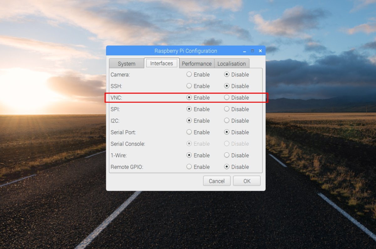
From the menu, open Raspberry Pi Configuration and select the “Interfaces” tab. On that tab, enable VNC. That’s it, the Pi is configured. The Raspberry Pi Foundation has a great writeup with a bunch more detail about VNC and its more advanced functions here.
Step 3 – Install A VNC Viewer
Step 4 – Test It Out
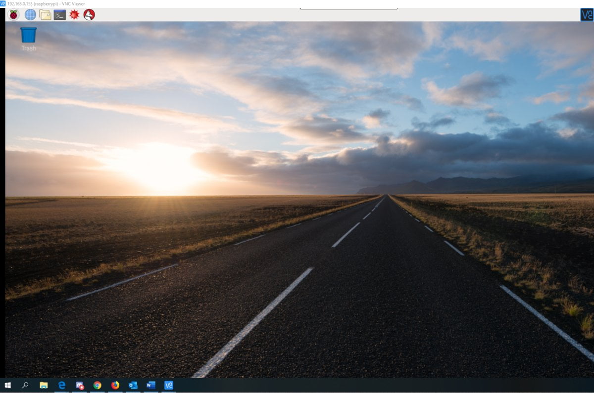
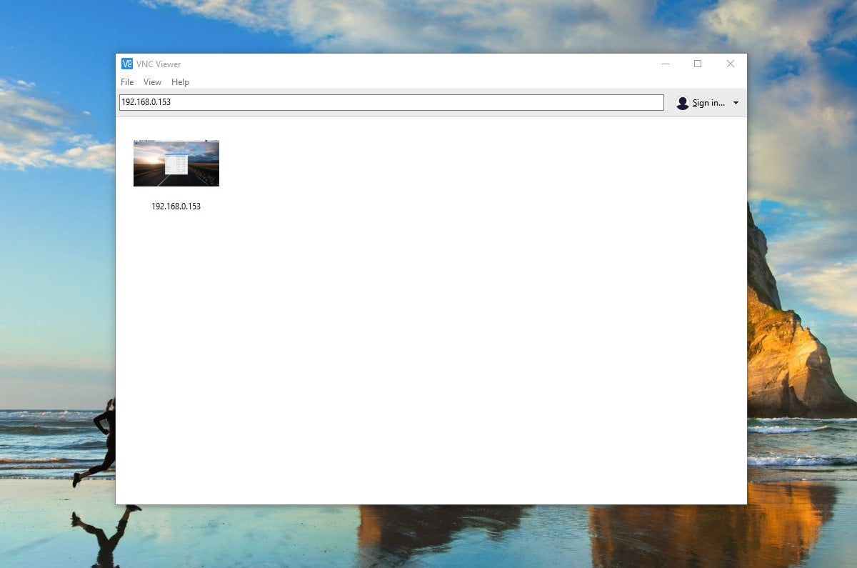
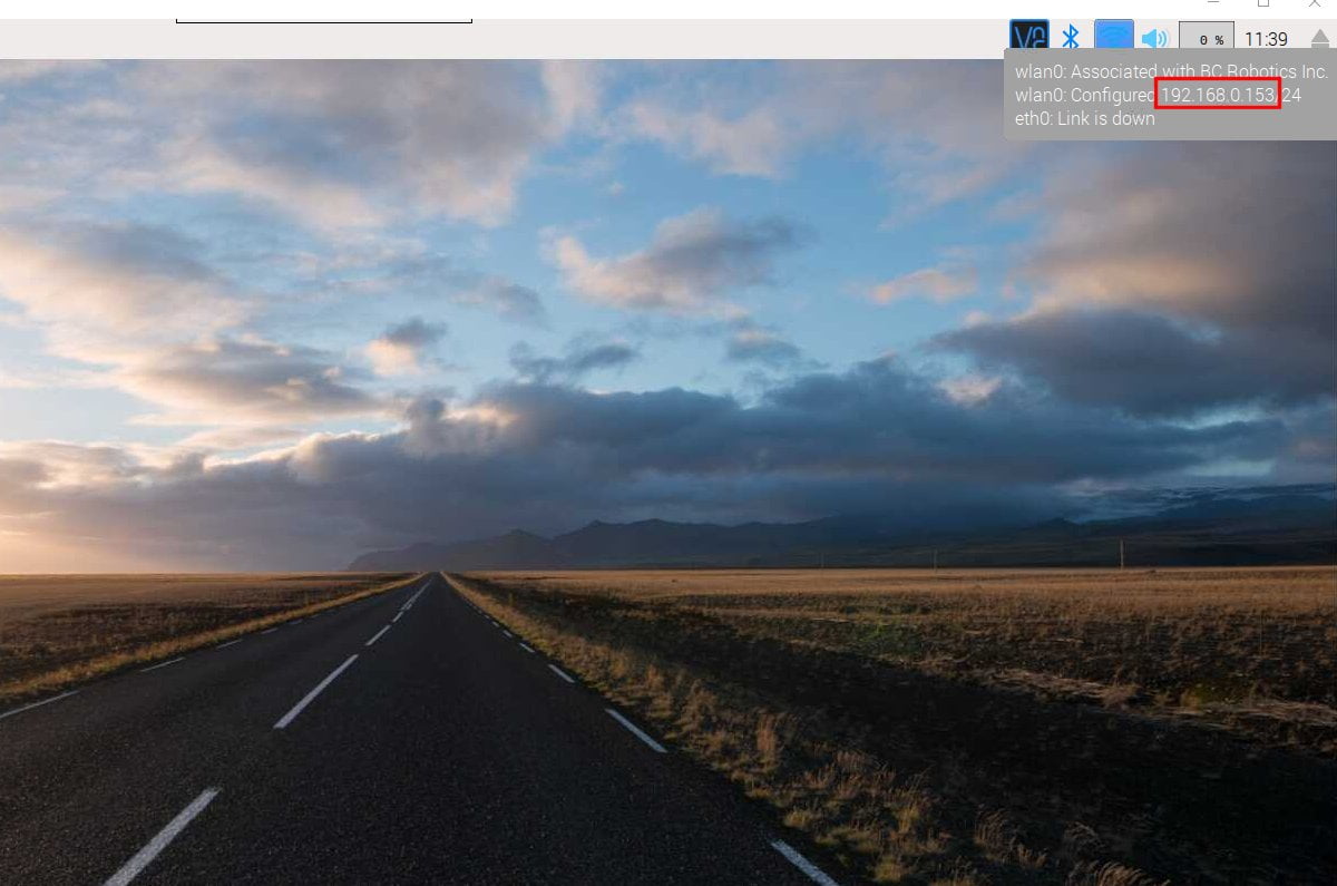
On the Raspberry Pi, grab your IP address by hovering the mouse cursor over the network connection logo in the top right corner. Load up VNC Viewer on your controlling device (computer) and type the IP address of your Pi in. You will be prompted with a security warning and then a username and password. The username and password are your normal credentials for the Pi. So if you haven’t changed anything it would be username: pi , password: raspberry
Once that is entered, the Raspberry Pi desktop should appear on your screen. Pretty cool huh?
Time to shut it down and move it outdoors.
Step 5 – Where To Locate The Pi
Now that we can remotely access the Pi, it can be installed anywhere and still relatively easy to work on. This part is very relative to your setup / location – but the Pi should be installed somewhere that the Pi can be easily powered and wires can be easily run to wherever the solenoids are located. You will also need to consider the sensor locations and how the wires will be run. Finally, the Pi also needs to be protected from the elements – so if it is outdoors you may want to consider a weatherproof box.
Step 6 – Connecting The Solenoid Wires
Solenoids can be connected up a few different ways. Most commercial systems will have a common power wire with a return wire for each solenoid. For situations where solenoids are not located near one another or for custom builds this many not be the case. The Irrigation Board can handle both situations.
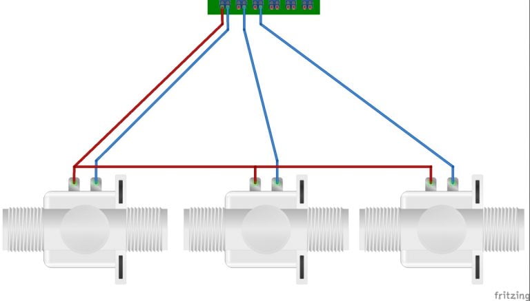
If you have a single common power wire (commercially installed irrigation systems): connect the common wire to S1’s “+” pin. Now connect each of the return wires to their respective channels “-“ pin as shown here:
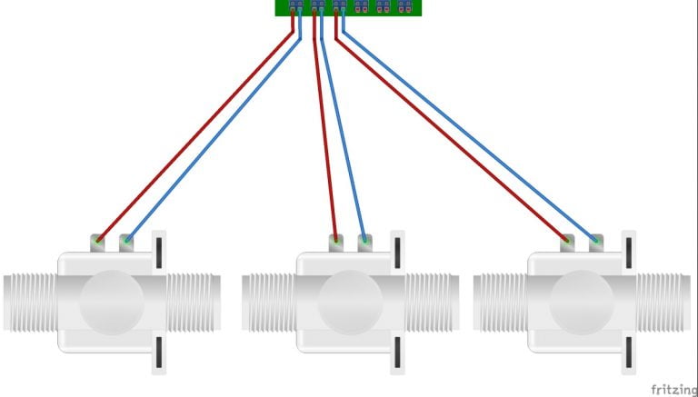
If you have individual power wires, just run each pair of wires to their respective “+” and “-“ pins. As shown here:
Step 7 – Sensors
Depending on where your control box is located, you may need to extend wires to position your sensors where you want them. If you are lucky, many professionally installed sprinklers have extra unused wires in their control cables that can be commandeered to connect sensors. Otherwise, additional cable may need to be run to get your sensors. If running cables is a pain – it may be easier to relocate the Pi closer to where the sensors are needed.
Step 8 – Powering The Solenoids
Most commercial systems use a 24VAC power supply – so if you are replacing an existing irrigation controller you can’t reuse the power supply. This is due to the design of the circuits and the power requirements of the Pi. Instead, we are going to replace it with a DC Power supply. A 12VDC 3A supply should be more than sufficient to drive most irrigation solenoids along with the Pi. We do suggest testing this first as it will depend on the type of valve, the age of the valve, and the water pressure; higher voltages may be required to get the valve to trigger. To connect it to the board, either cut the DC Barrel off the end of the cable or use one of these DC Barrel Adapters if you prefer.
Step 9 – Powering The Pi
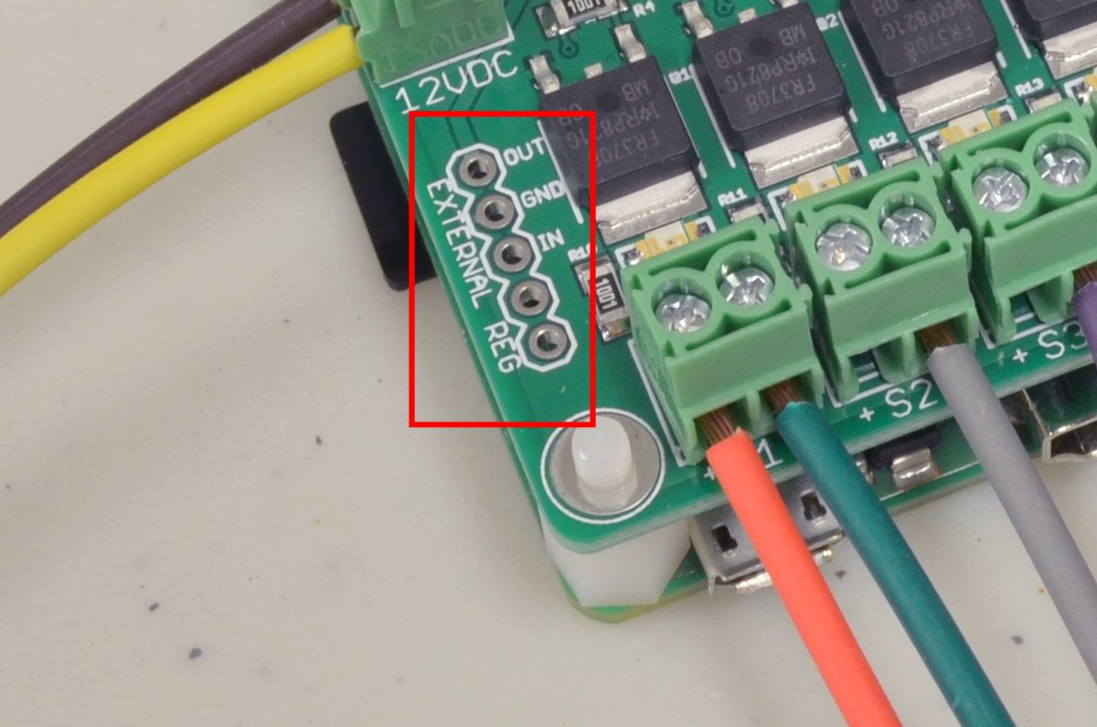
There are a few ways to do this – the easiest is to use the same 12V 3A supply to power the Pi by way of the optional power regulator slot on the Raspberry Pi Irrigation Board. We are using a 2.5A version of the 5V Buck Regulator by Pololu. This allows the Raspberry Pi to run of the input voltage for the solenoids. This regulator has a very wide input range – so even if you are running up around 24VDC for higher powered solenoids it will keep everything going quite nicely!
Alternatively, you can power the Pi separately using a normal Raspberry Pi Power Supply and skip the Pololu voltage regulator – just note that this will not power the solenoids. You will still need that 12V 3A power supply in addition to the Pi power supply in this case.
Step 10 – Power It Up And Test
Double check all your connections and if everything checks out, go ahead and power it up. Test your VNC connection and then fire up Idle3 and load your program. Now run the program and test your system. Within a second or so you should see the first red light on the board turn on and water should start flowing (assuming your plumbing is hooked up!) At the end of the cycle you should receive your email with all your stats. You will likely need to adjust run times and settings going forwards – but with VNC running that is done from the comfort of your desk!
Close Idle3, close your VNC connection and leave the Pi running. It should run automatically at the pre-defined times we set up in the last step from now on.
[info]Have A Question?
If you have any questions, or need further clarification please post in the comments section below; this way future users of this tutorial can see the questions and answers!
[/info]


Matt Schmitt
Trying to set-up my system after receiving the parts. Bought the 12VDC power supply and am using the Pololu 5V, 2.5 A step down. Thought the IrrigationHAT would have the 12VDC plug adaptor on it but its just the wire blocks. assuming the solution is cut the plug off of power supply and wire into the block. Is that what you recommend?
Matt Schmitt
Nevermind. I now see step 8 above.
Kurtyboy
I’d like to use this system with latching solenoids. These use very little power while the solenoids are on. These work by simply sending a short “pulse” in one direction to turn the solenoid on and reversing the polarity for a short pulse to turn it off. Can this be setup using your hardware or do I need to do something else?
William @ BC Robotics
This board wouldn’t be ideal in that case… look at using H-bridges instead: H-Bridge Motor Driver – 1A
Latching solenoids would be connected to it just like regular bi-directional DC motors. With each chip above you could drive two solenoids. Hope that helps!
sylvain
I have a couple of questions, hopefully this s the right place to ask.
1/ I am using the irrigation HAT with a Pi 4. The Pi 4 requires a 3A power supply and I have a 5″ touch screen attached to it on an USB port. Would the Pololu 5V, 2.5 A step down be enough to power the Pi4 with the screen?
2/ The wire blocks on the HAT is not marked with any polarity. Does this mean that the + and – cables from the 12 VDC power supply can be plugged in interchangeably?
Thank you in advance!
Chris @ BCR
Hi Sylvain,
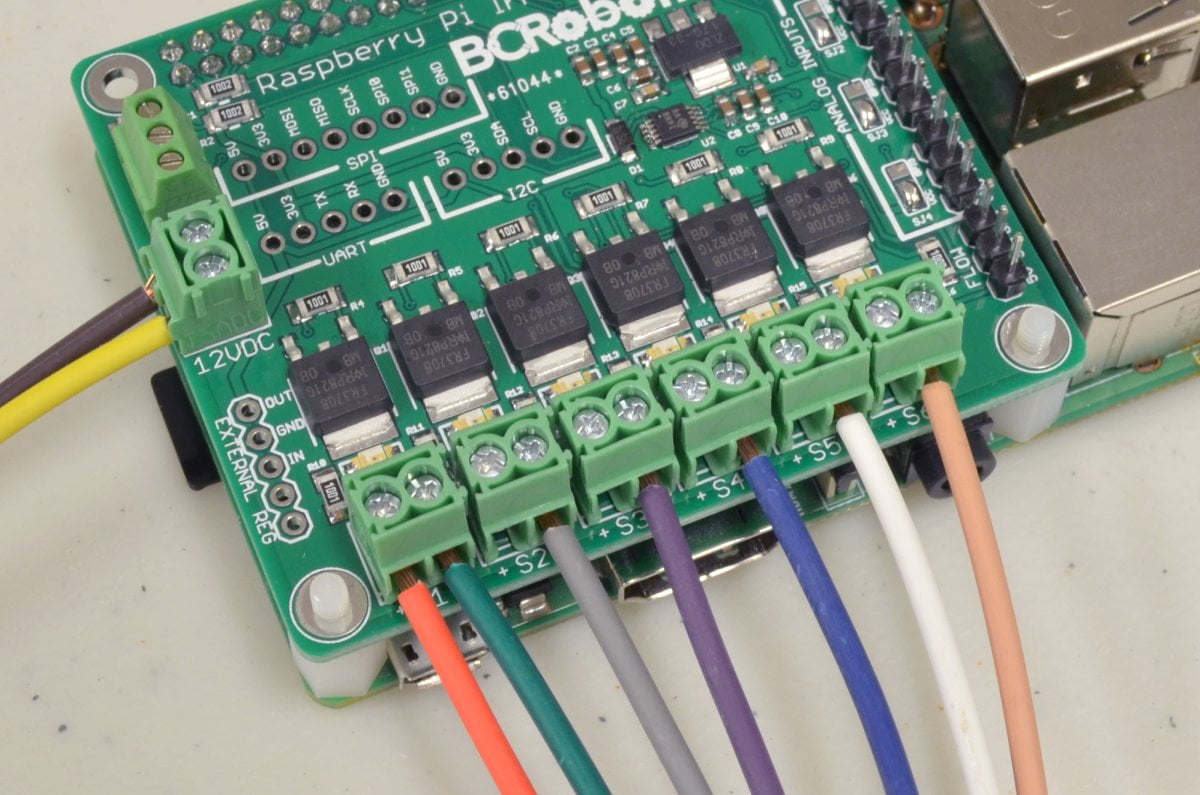
Thanks for the note – the polarity to the board is important. The blocks are labeled for the power input here:
GND is hard to see on this angle, but it would be the left side of the block.
As for power, if you are not using anything high draw on the USB ports, 2.5A will be more than enough for both.
Shane
While these are 12vDC, is there any support for DC latching solenoids? I understand these require the reversal of +/- for the solenoid to close. Can the power be reduced from 12v to between 6-9v to support a different solenoid type?