BC Robotics
Browse categories
- New Additions
- Shop
- On Sale / Clearance
- Popular Categories
- ArduinoArduino is the most popular open source microcontroller platform on the market. These easy to program devices can read sensors, control relays, light up LEDs, and even talk to one another. Their ability to interact with the real world by way of sensors and other electronics makes them ideal for automation such as watering a plant when it is dry, reading the weather, or controlling lights when it gets dark – the possibilities are endless. We carry a variety of Arduino compatible microcontrollers from several manufacturers, each with their own specific strengths and purposes. To further specialize your microcontroller, we carry a large selection of daughter boards (shields) which can add powerful sensors, GPS, or even LCD screens to your project! Just getting started with microcontrollers? We carry a variety of Arduino starter kits to get you reading sensors and blinking lights as easily as quickly as possible!
- BBC micro:bitThe BBC micro:bit is a pocket-sized computer designed for beginners in electronics and coding. The micro:bit makes getting into these often daunting fields as easy as possible. Programming the micro:bit V2 can be done by computer or by their intuitive app available for Android and iOS devices. Code can be designed using a drag and drop interface in the Blocks editor, Javascript, or Python.
- ESP8266 & ESP32The ESP8266 and ESP32 microcontrollers from Espressif are powerful, inexpensive, and feature integrated WiFi connectivity. These are ideal for IoT applications. We offer a variety of different ESP8266 and ESP32 modules for different skill levels.
- FeatherFeather is a flexible and powerful family of microcontroller main-boards (Feathers) and daughter-boards (Wings) designed with portability in mind. All Feathers have integrated battery connectors (and most have built in lipo chargers) The Feather form factor is not locked to a specific chipset or programming language. Feathers are available with a variety of chipsets and on-board features. Most Feathers and FeatherWings have example code and libraries written in Arduino C/C++ and CircuitPython.
- Makey MakeyThe Makey Makey kit is a electronics kit designed for beginners. It explores the concepts of creating circuits through everyday items. When plugged into a computer you can use the Makey Makey to make anything into a keyboard or mouse. No programming required! Projects like a Banana Drum Set, Cat Detector, Musical Stairs, and countless others are easier than you think! We carry the Makey Makey Classic Kit – a starter kit for the Makey Makey – along with extra alligator clips, copper conductive tape, and replacement cables.
- Raspberry PiThe Raspberry Pi was first introduced in early 2012 as a simple, low cost, computer fit onto a circuit board roughly the size of a credit card. The idea was to use this low cost computer to promote teaching of computer science in schools but it has grown to be so much more! Since its release, well over 30 million of these little computers have been sold. We have carried the Raspberry Pi in Canada since it first became available and have watched as the Pi has morphed into a complete development platform with powerful single-board computers, cameras, touchscreens, and other accessories. Its multitude of inputs and outputs for electronics and computer peripherals and its impressive computing power mean it can be used to make just about anything you can imagine. The newest and most powerful version, the Raspberry Pi 4, is now available!
- Popular Brands
- AdafruitAdafruit was founded in 2005 by MIT engineer, Limor “Ladyada” Fried. Her goal was to create the best place online for learning electronics and making the best designed products for makers of all ages and skill levels. In the last 10 years, Adafruit has grown to over 100+ employees in the heart of NYC with a 50,000+ sq ft. factory.
- ArduinoArduino is an ever growing platform used by some of the most popular microcontrollers out there. For many of us, this is where it all started – the Arduino was (and still is today) a pioneer when it comes to making programming hardware easy and accessible. We have one of the largest selections of Arduino and Arduino accessories in Canada. These range from basic Arduino Uno, to Cellular and WiFi connected devices perfect for the Internet of Things, and all the accessories needed to get them running!
- Micro:bitMicro:bit Educational Foundation are the manufacturers of the popular BBC micro:bit; a pocket-sized computer designed for beginners in electronics and coding. The micro:bit makes getting into these often daunting fields as easy as possible. Programming the micro:bit V2 can be done by computer or by their intuitive app available for Android and iOS devices. Code can be designed using a drag and drop interface in the Blocks editor, Javascript, or Python.
- BC RoboticsIn addition to stocking 2000+ unique items, we also manufacture our own accessories right here at BC Robotics. In 2014 we began developing our own widgets and add-ons for Arduino, Raspberry Pi, and general prototyping. This has now grown to over 80 different SKUs. Our boards are assembled in-house with top quality components. Many feature detailed tutorials or project guides to get you up and running as quickly as possible!
- Raspberry Pi
- SparkFunSince 2003, SparkFun has been helping turn ideas into reality – whether you’re creating a smart weather station, exploring the frontier of machine learning, building a robot for school or prototyping your first (or tenth) product. No matter your vision or skill level, our open source components, resources and online tutorials are designed to broaden access to innovative technology and make the road to a finished project shorter. We’re here to help you start something.
- Frequently Asked Questions
- My Account
- Wishlist
- Cart
Free Shipping - US & Canada @ $150 CAD
PRODUCT TUTORIAL
- Chris @ BCR
- October 31, 2022
- 2:07 pm
- 3 Comments
With the release of a Raspberry Pi Pico with wireless capabilities the possibility of porting many of the CPU less intensive projects previously done with the Raspberry Pi / Pi Zero to this inexpensive platform! Our Raspberry Pi based weather station is one of these projects; using a quad-core computer to read a few sensors is not really using the Pi 4 to its fullest potential.
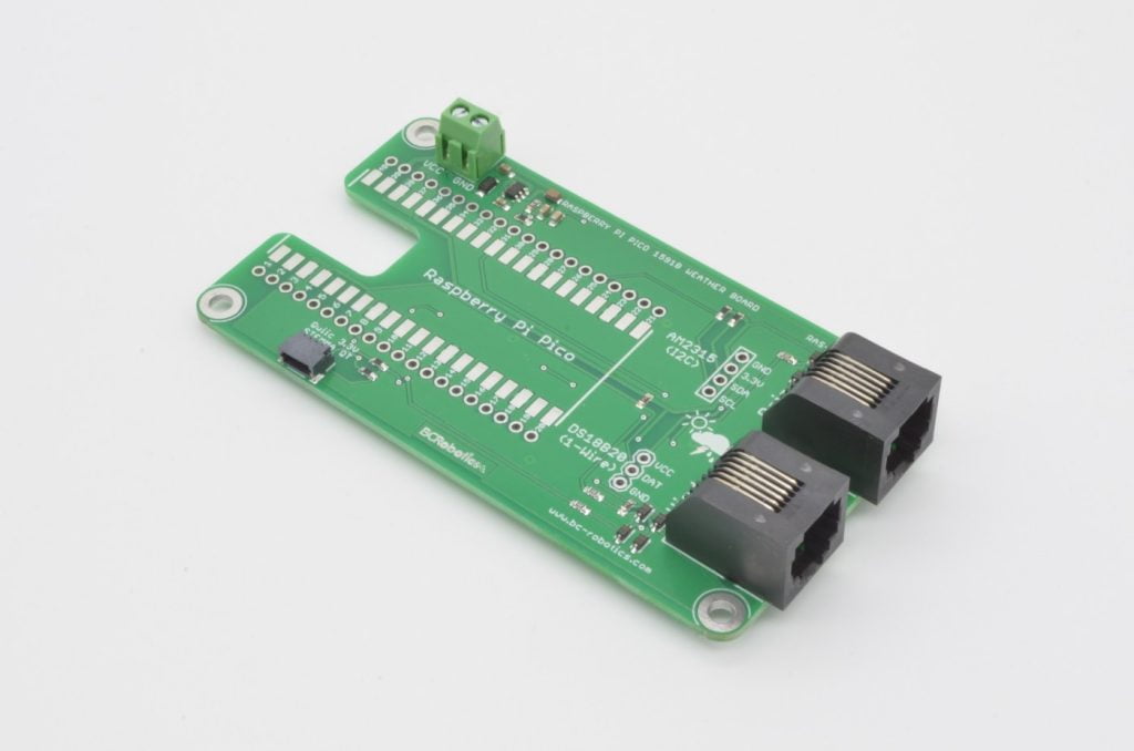
In this multi-part tutorial we will be building a similar weather station to our original Raspberry Pi based project. We will be using the Raspberry Pi Pico W to take full advantage of the wireless capabilities and our Raspberry Pi Pico 1591B Weather Board to extend its capabilities. Our basic Weather Station will measure Wind Speed, Wind Direction, Rainfall, Temperature, Air Pressure, and Humidity. Going forwards, additional sensors could be added without much trouble using the Qwiic / STEMMA QT port on the Weather Board.
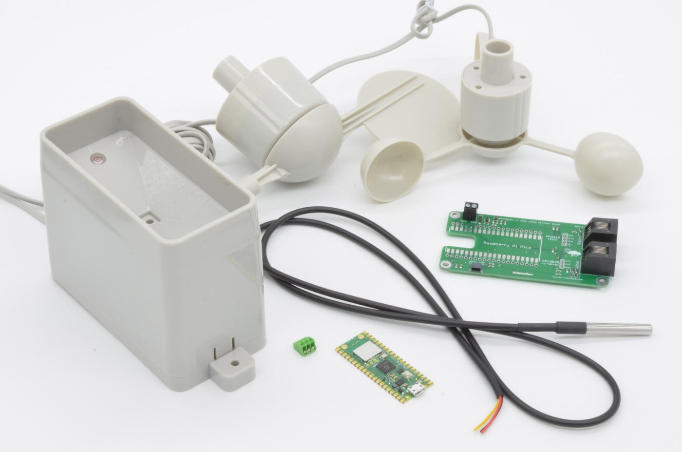
The Parts Needed
The Raspberry Pi Pico 1591B Weather Board can be used with the Pico or the Pico W. In this tutorial we will be using the Pico W as we want the WIFI connectivity. A standard Pico can be used, and much of the code as well, but we do recommend following the tutorial exactly if you are not experienced.
- 1 x Raspberry Pi Pico - or - Raspberry Pi Pico W
- 1 x USB micro Cable
- 1 x Raspberry Pi Pico 1591B Weather Board
- 1 x Adafruit BME280 Temperature Humidity Pressure Sensor
- 1 x Qwiic / STEMMA QT Cable – 50mm
- 1 x SparkFun Weather Meters
- 1 x DS18B20 Temperature Sensor (wired probe version)
- Solder + Soldering Iron
Going forwards there will also be tools and other components required – we will discuss these throughout the next 3 parts of this tutorial.
Step 1 - Project Outline
In this multi-part tutorial we will be breaking down the construction of our Pico W based Weather Station into four distinct sections.
- Part 1: Overview & Assembly
- Part 2: Code & Testing (Arduino)
- Part 3: ThingSpeak (Arduino)
- Part 2: Code & Testing (MicroPython)
- Part 3: ThingSpeak (MicroPython)
- Part 4: Placement & Installation
9.1%
Step 2 - A Quick Overview
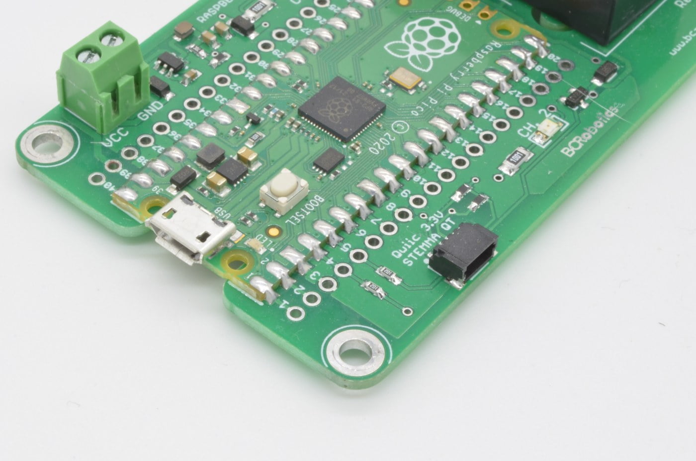
There are a few things we will need to solder to the Weather Board to get up and running. Starting with the most important part first, we will need to attach the Raspberry Pi Pico W.
Similar to the ESP series of microcontrollers, the Raspberry Pi Pico uses castellated edges on the board, allowing this to be surface mounted to the board below. Don’t be thrown off by the surface mount soldering – this is a very easy method of connecting two boards, well suited to conventional soldering irons and solder. No special SMT soldering equipment / reflow / etc. are required.
Caution:
We do not recommend using reflow methods to solder the Pico to the Weather Board. The plastics used in through hole connectors tend not to like the temperatures involved and may result in deformed or damaged connectors.
18.2%
Step 3 - Soldering The Pico (Part 1)

Please Note:
We are going to borrow a few of the soldering photos from the 1591 Relay Board Tutorial (as the process is identical).
In the next few steps we will get the Pico W attached to the Pico 1591B Weather Board.
This is very easy to do, simply line up the board on the outline as shown in the image. We are just going to solder one pin in one corner to ensure everything is lined up as it should. Don’t solder all the points at once, as adjusting the placement of the board is extremely difficult once several solder pads are filled. This method allows the single point to be reheated and the board moved if adjustment is needed.

We are going to start by soldering pin 1 in the corner. Carefully fill the pad with solder and allow it to flow between the Pico and the Weather Board. Your end result should be similar to the pad shown in our example photo.
27.3%
Step 4 - Soldering The Pico (Part 2)
Once the alignment is good, solder an opposite corner to ensure everything is locked in place. In this case, the opposite pin is 21, close to the two RJ11 ports for the Weather Meters.

If everything is still aligned as it should be, we can now solder all the remaining pads. Your result should be similar to the example image.
After this is complete, inspect your work and ensure there are no bridges between adjacent pads. Once you are satisfied the soldering completed correctly, we can move on to the next step!
36.4%
Step 5 - DS18B20
Next we are going to install a 3 Pin 2.54mm Pitch Screw Terminal to connect the DS18B20 Temperature Sensor. The DS18B20 is weatherproof, so the probe will actually be mounted outside of the box, with the wires running into the board, so having them removable will make the installation into a box much easier going forwards. If you prefer, you could also solder the wires direct to board.
45.5%
Step 6 - DS18B20 (Continued)
The DS18B20 can ship with two different sets of wire colors – these are often seen with Red, Black and White or Red, Black, and Yellow. Normally Red will be power, Black will be Ground, and White / Yellow will be the Data pin. Be sure to check the pinout, we list it on our product page for the DS18B20.
A 4.7K Ohm Resistor is normally needed to between the 5V and Data Pin when using the sensor; this is taken care of by the Pico Weather Board – so no need to wire one in!
Connect your DS18B20 according to the color code of your sensor.

54.5%
Step 7 - Rain and Wind Speed

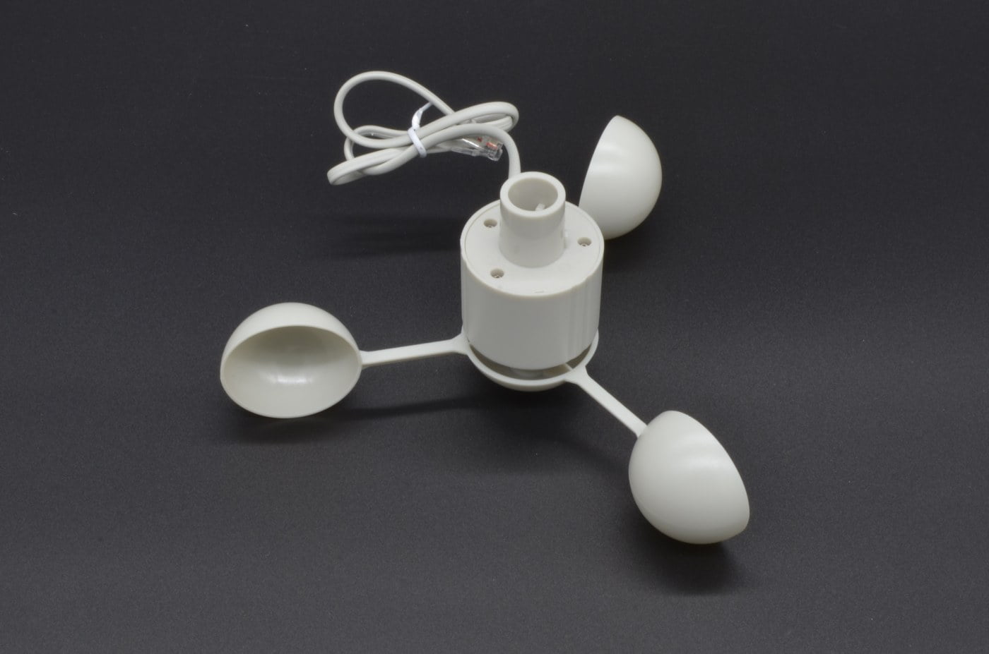
The Wind Speed, and Rain Gauge are both basic digital sensors. The Anemometer (Wind Speed) is measured by counting how fast it spins in a given amount of time while the Rain Gauge measures how many times the gauge tips a precise amount of water over a given period of time. There is no soldering for these ones sensors – they will just plug into the Weather Board. More information on the sensors and how they work can be found on their datasheet.
Note:
The Anemometer does not plug directly into the Weather Board, it has a much shorter wire harness that actually plugs into the base of the Wind Vane and both signals are then transferred via the Wind Vane's longer wire harness.
63.6%
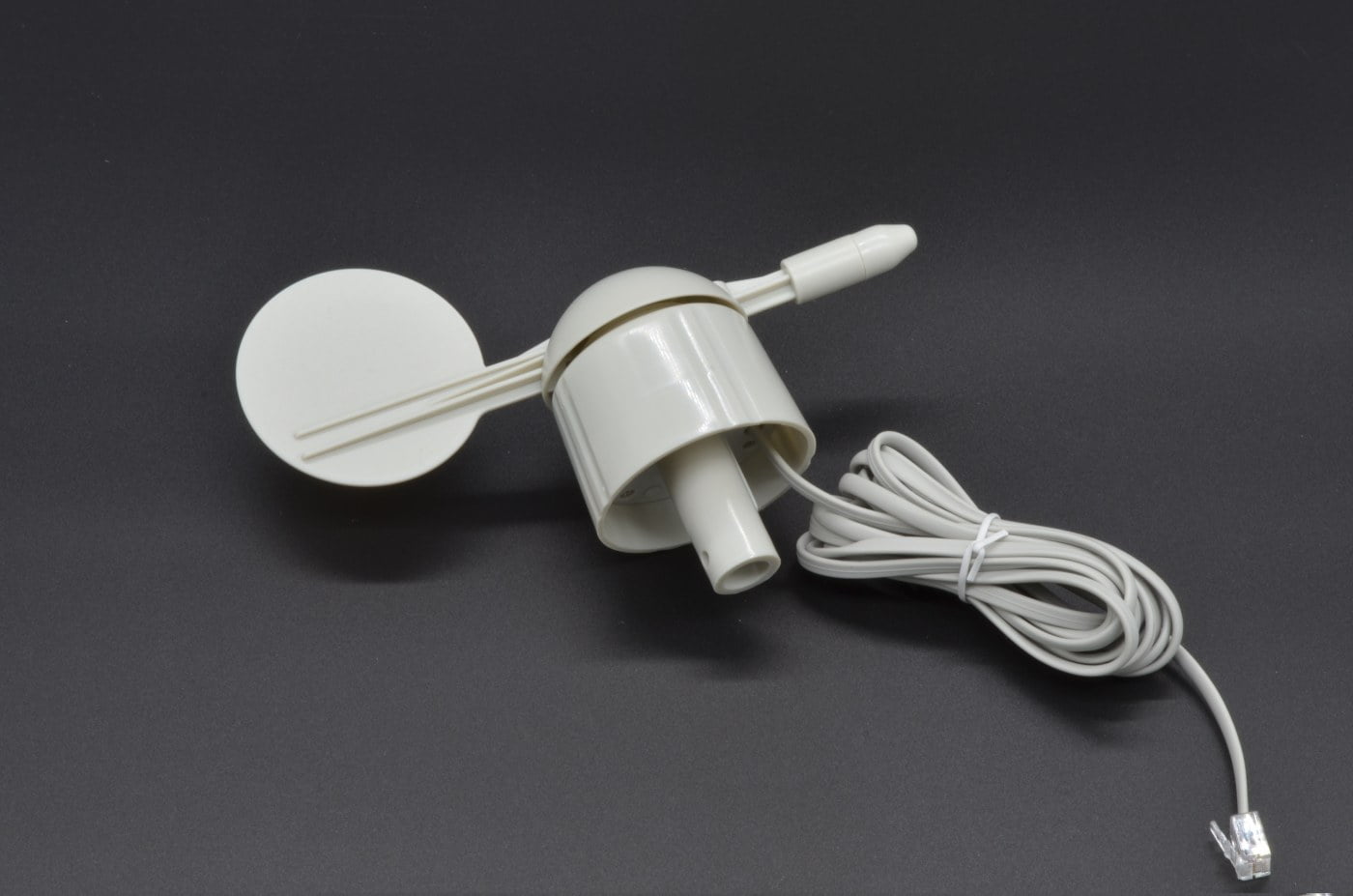
Step 8 - Wind Direction
Wind Direction is handled a little differently, this sensor is analog and provides a variable resistance depending on which of the 16 directions the vane is facing. We use a voltage divider circuit on the Weather Board to convert this to a variable voltage, which we can then read using the Pico’s built in Analog to Digital converter to get the direction. More information on the sensor and its resistance table can be found on the datasheet.
72.7%
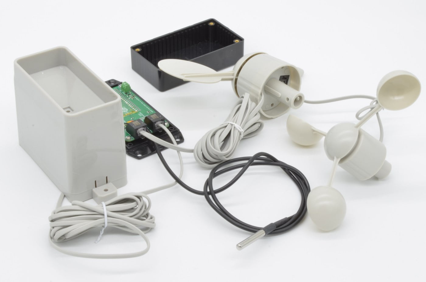
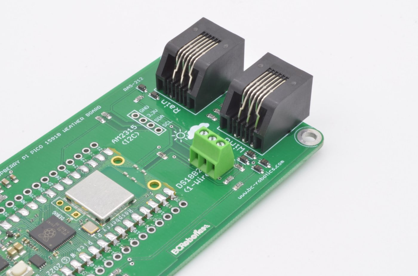
Step 9 - Connecting the Wind & Rain Sensors
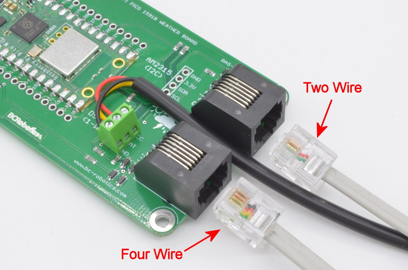
Connecting these sensors is quite straight forward – if you look carefully, one of the two RJ11 plugs at the end of their cables has 4 wires in it, while the other has two. Plug the 4 wire line into the “Wind” plug on the Weather Board, plug the 2 wire line into the “Rain” plug.
81.8%
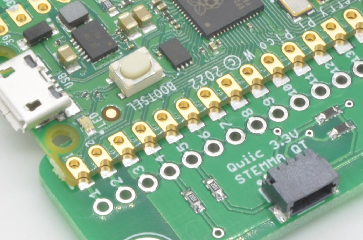
Step 10 - BME280 (and other Qwiic sensors)
With many of the most popular sensors out there now being available with a Qwiic or STEMMA QT connector, numerous sensors can be added to a project using a single plug. Just about all of our new products feature this connection point, so gone are the days of having to solder protoboards and figure out pinouts for various sensors – just plug and play!
The BME280 breakout by Adafruit is one of these compatible sensors. To connect it, we are going to use a Qwiic cable and simply plug it into the BME280 running the other end to the Weather Board. There are numerous lengths of cable available in the Qwiic ecosystem, but for this instance we are using the 50mm version.

90.1%
Step 11 - Double Check Your Work!
Before we power anything up, it is always a good idea to go through and make sure there are no issues with the work that has been done. Make sure all the solder joints are clean, with no un-intended bridging. Check to make sure all the sensors are plugged in correctly as well.
In the next section of the tutorial we will be powering up the Weather Station and writing code to start reading all of the sensors. The Pico works well in both Arduino and MicroPython so we will go into both versions in separate variants of the tutorial.
100%
3 thoughts on “Raspberry Pi Pico Weather Station – Part 1”
Graham
Great tutorial. Well written and easy to follow. Where can I find the next part of coding the weather station?
William @ BC Robotics
Thank you for the feedback! The next part should be posted in a few days
jim.craig47
Great tutorial & project.
Looking forward to the next installment * the wind direction/speed sensor coming into stock