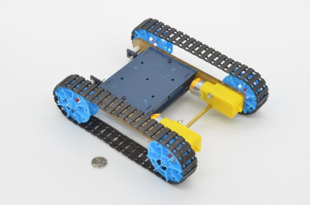
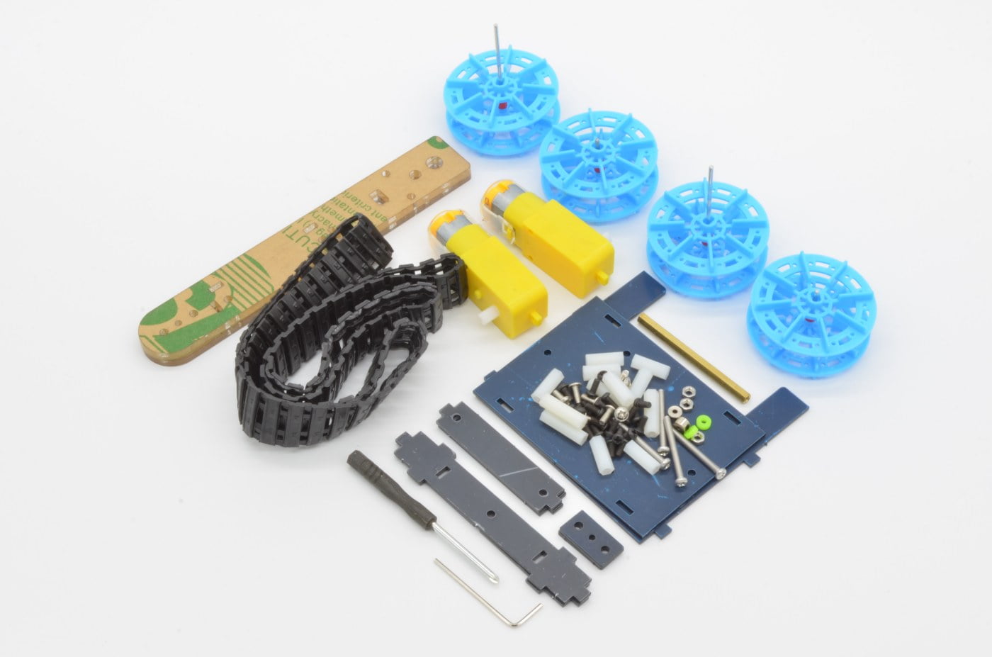
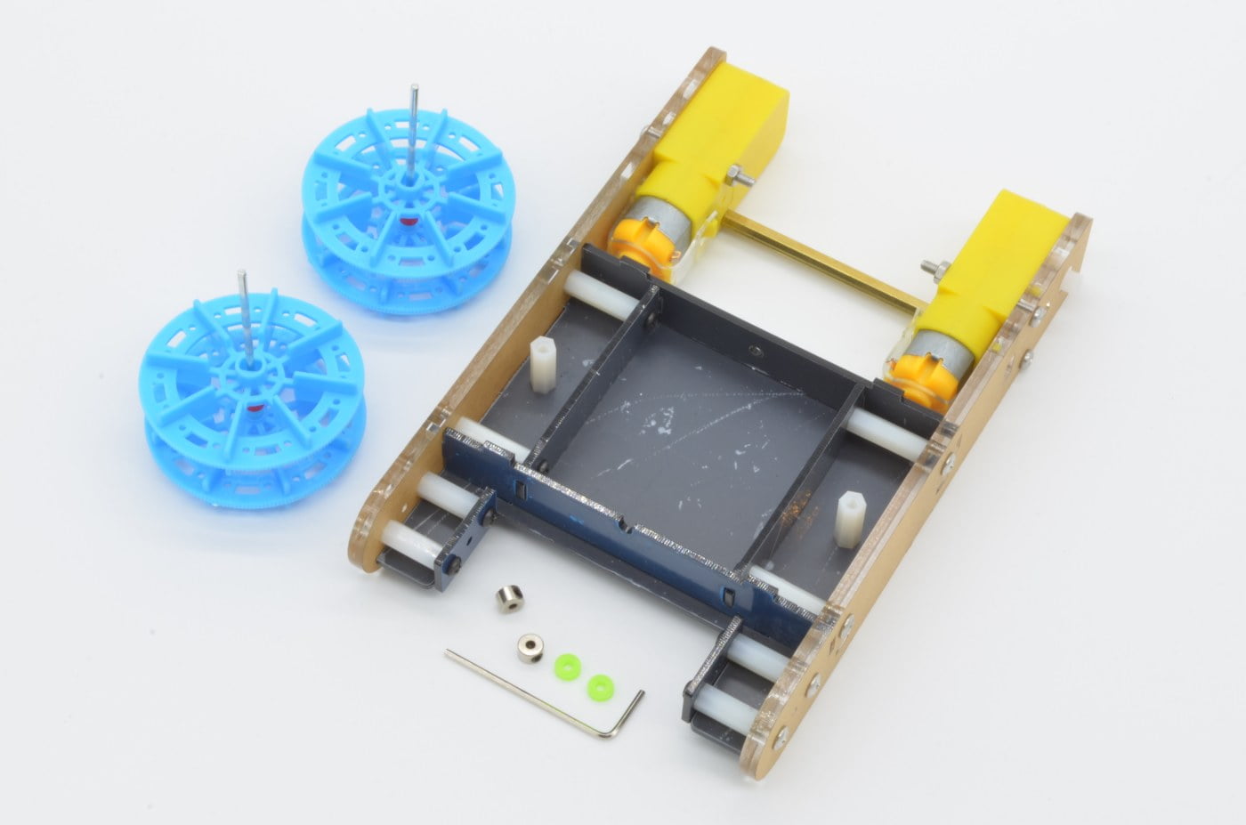
Wheeled robots are fun and all… but tank tracks are just so much better! In this tutorial we are going to assemble our Tank Track Chassis. The chassis features a variety of different sized screws and standoffs so pay careful attention to which parts are required in each step.
About The Chassis:
This chassis is very similar to most of our two wheel drive chassis, utilizing a single motor for each side. Just like those chassis, this Tank Chassis can be turned left and right by differential motor speed. This chassis should be compatible with just about any project using two “TT” style gearmotors to drive.
Recommended Tools
This kit includes a couple very basic tools to complete assembly, but nice tools always make the job more enjoyable! Screws this size are quite delicate and using the wrong sized screwdriver can cause them to strip out or wreck the finish.
We are going to start by assembling the inner structure of the chassis – this is the box that everything else connects to, and provides a base for further expanding the chassis or housing electronics. There are several parts that fit together in a specific manner, but we will work through it step by step!
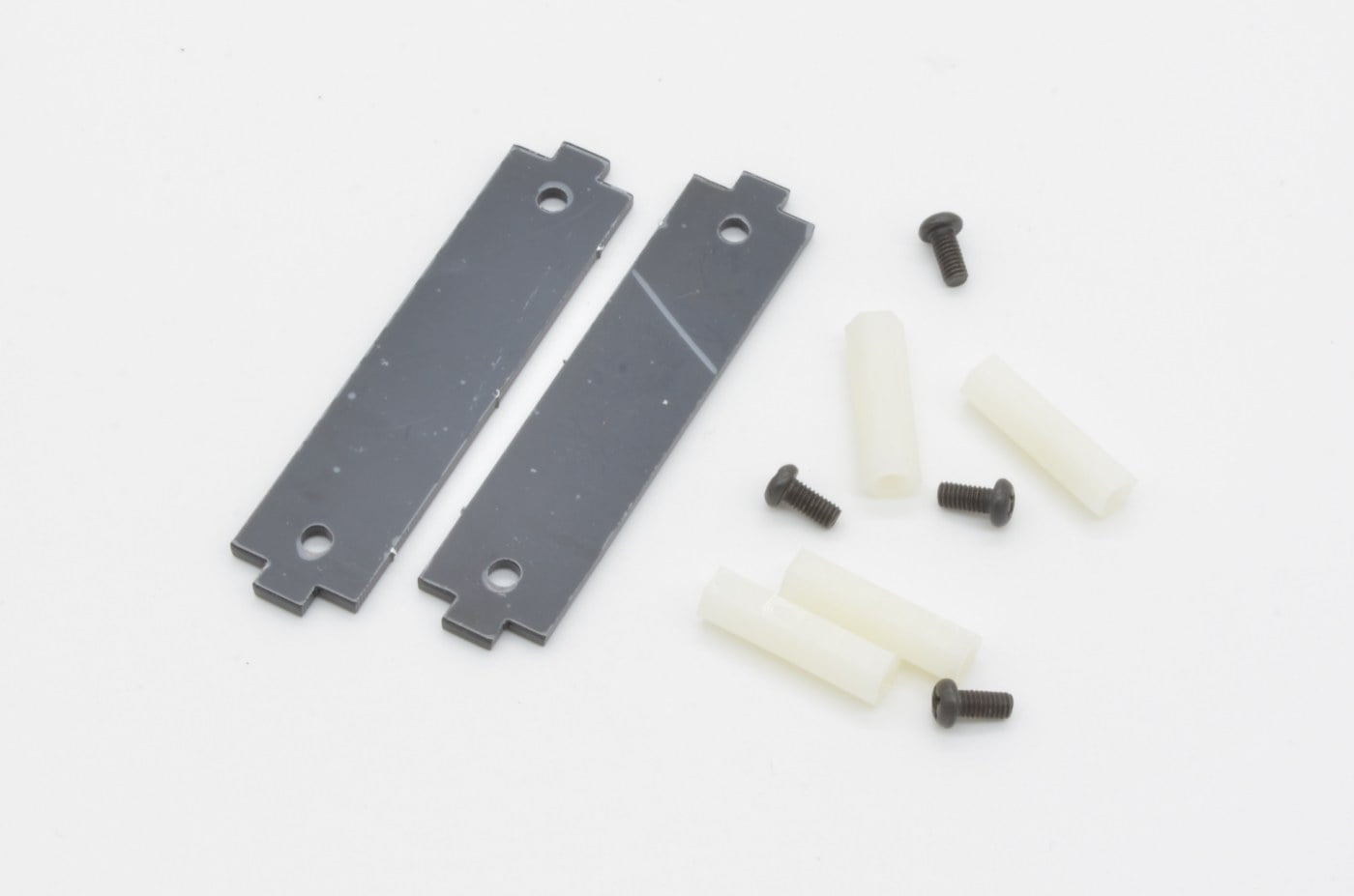
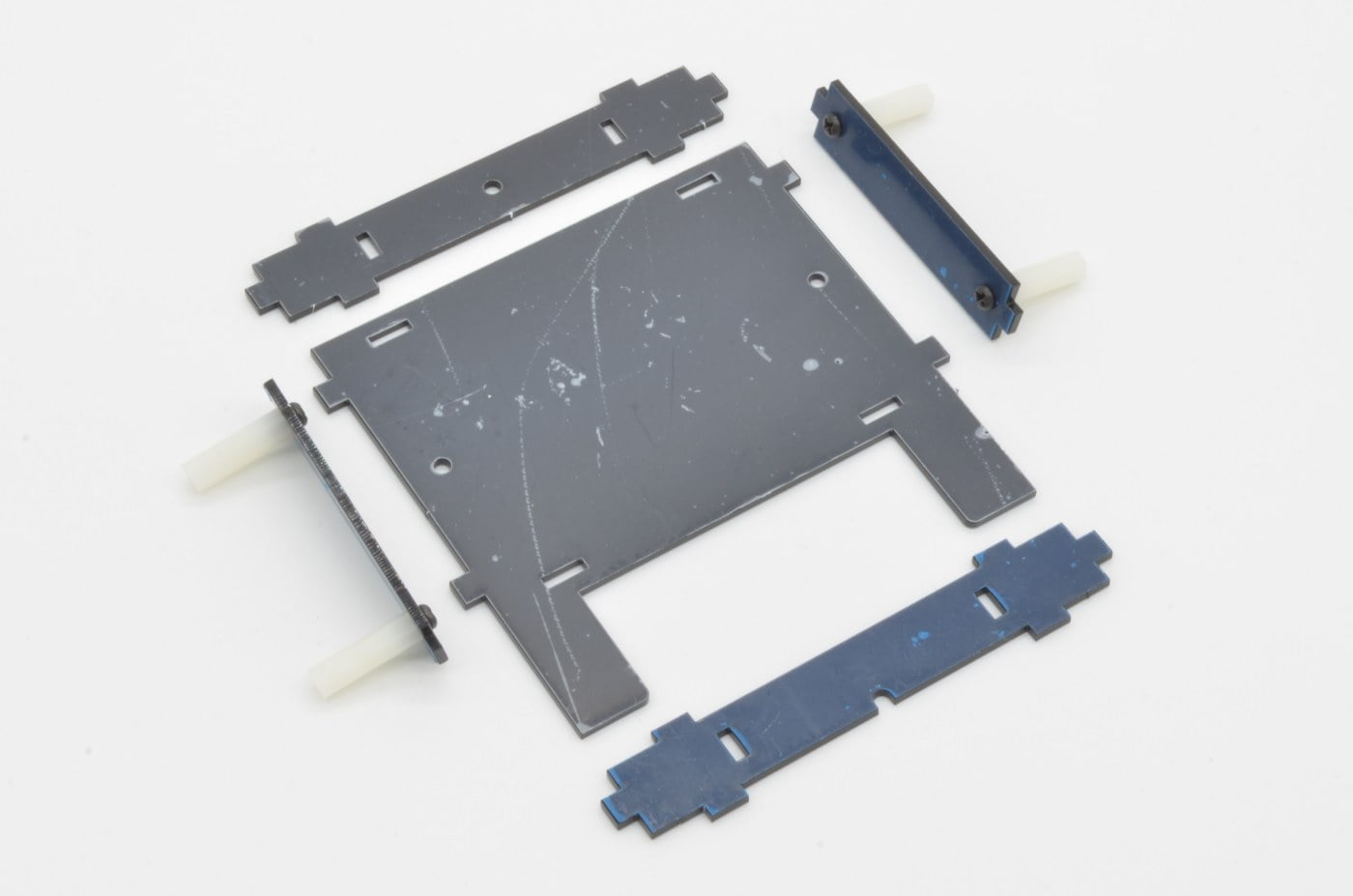
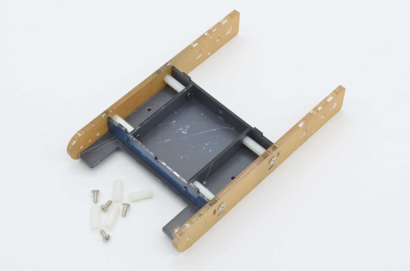
First, start by finding the two small acrylic plates (seen in the image to the left) and 4 x 20mm Standoffs, 4 x M3 Black Screws
These work as spacers between the otter track holder and the inner structure. There is no incorrect way to attach these, as long as both screws and standoffs are on the same side.
10%
Step 2 - Inner Structure (Continued)
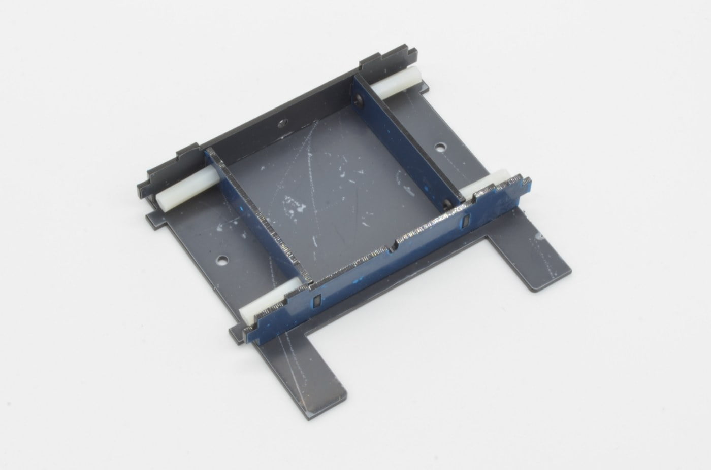
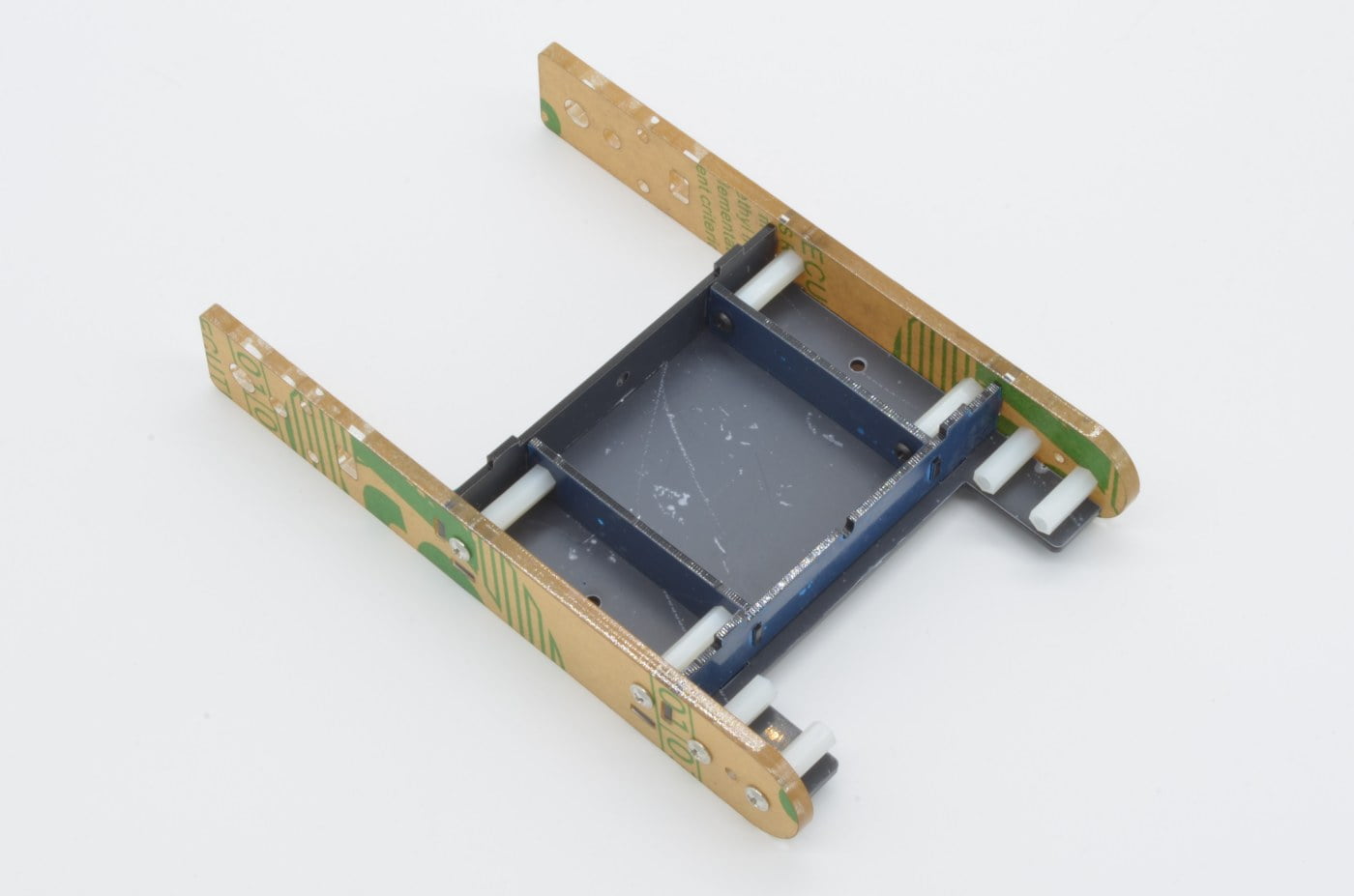
The inner structure fits together a little like a jigsaw puzzle – the two components we built in the last step are combined with the three additional laser cut panels to form the basis of the structure.
Align the components as seen in the previous image and all slots will fit together. This will be further held together by the outer frame in the next step.
20%
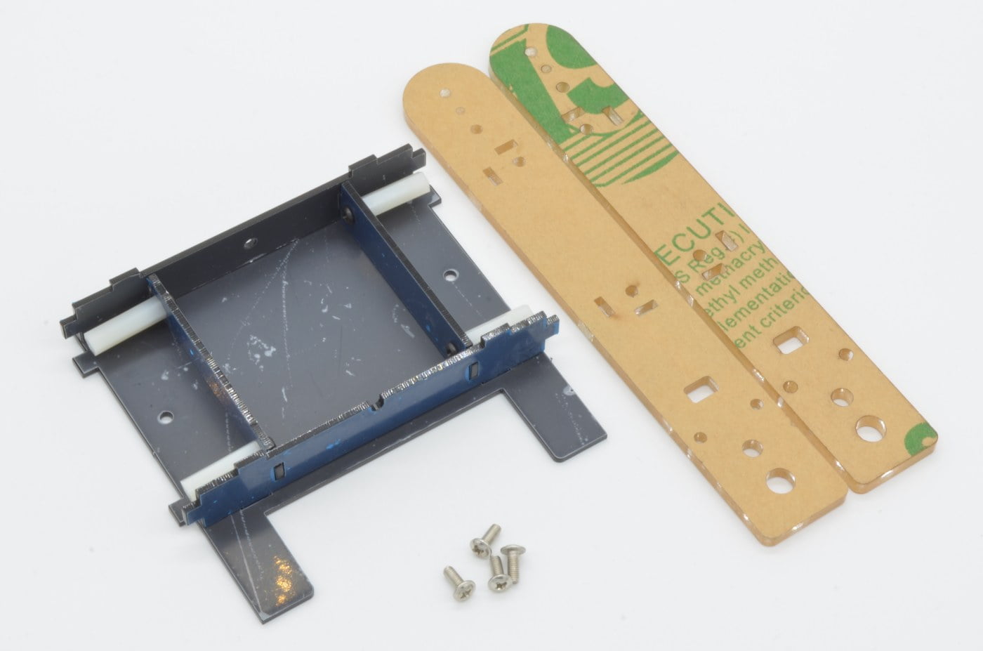
Step 3 - Outer Structure
The outer portion of the structure holds the track guides and motors in place. The outer frames have several cut-outs that align with the inner structure as well as screw holes that allow for the flat M3 screws to tie everything together.
Find 4 x Silver M3 screws and the two outer frames.
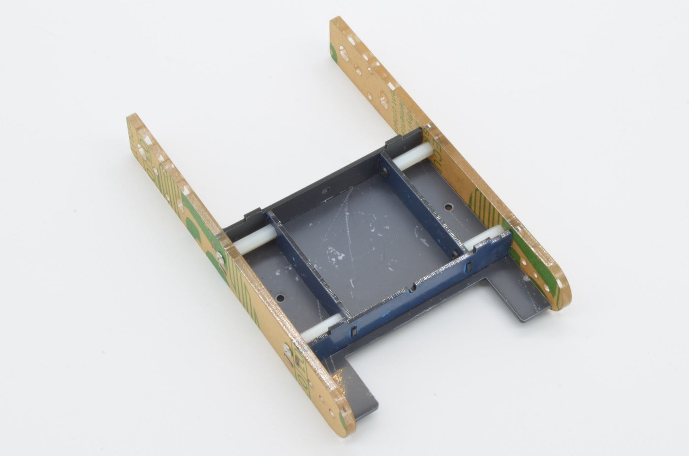
Be sure to align the outer frames as shown and carefully thread the screws in to the standoffs through the outer frames.
30%
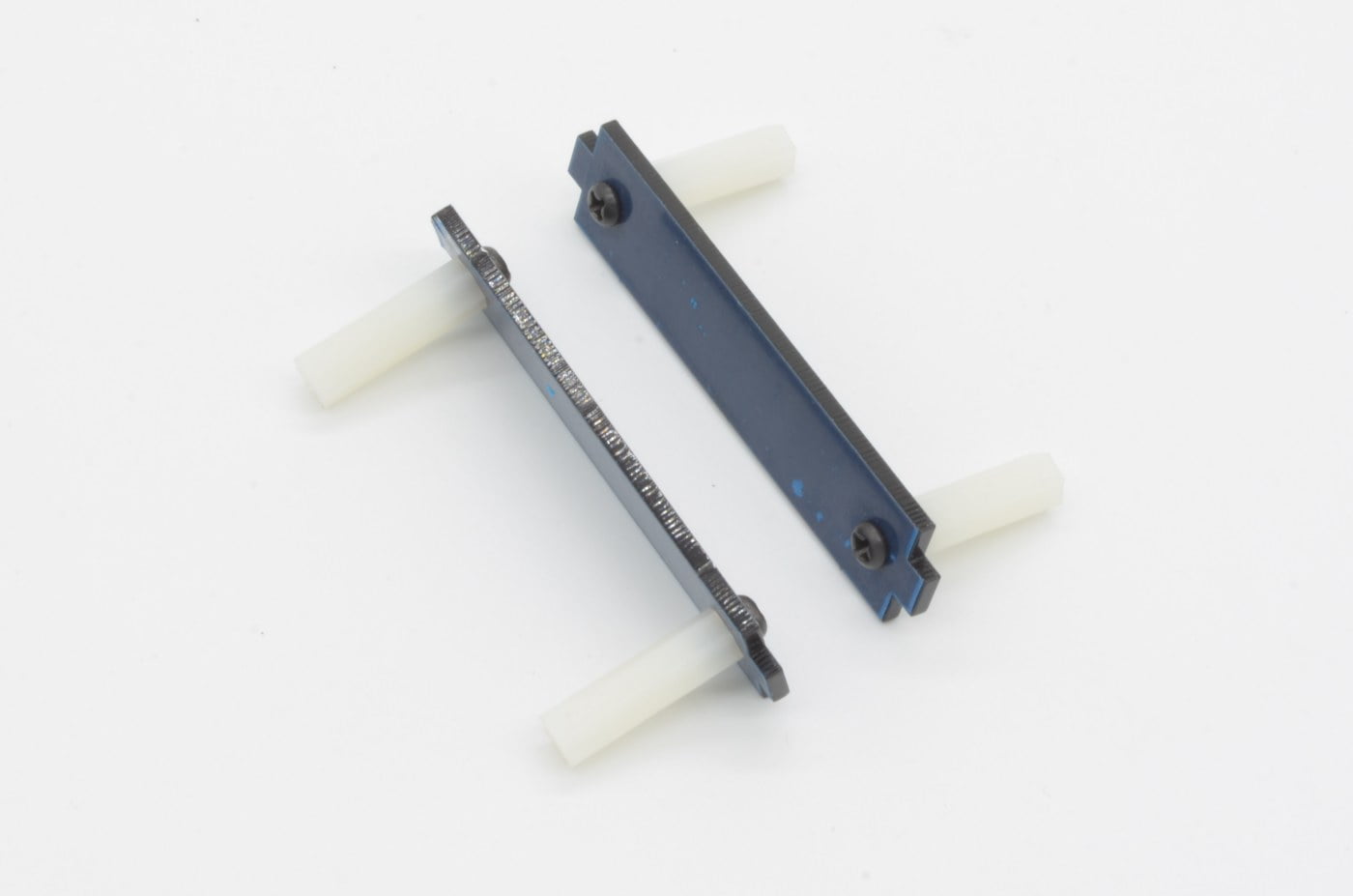
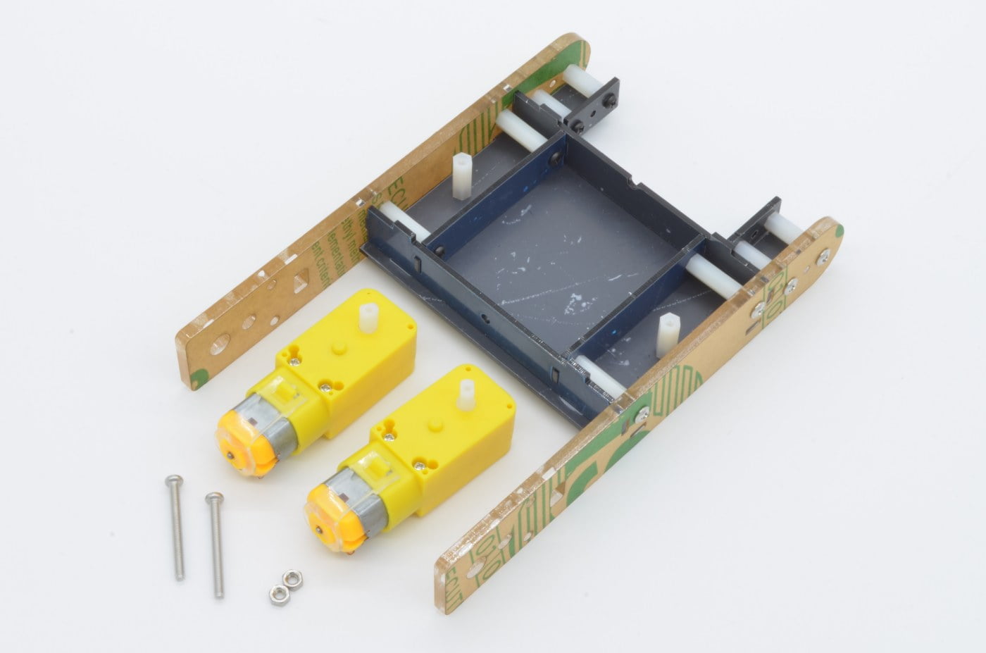
Step 4 - Idler Wheel Brackets
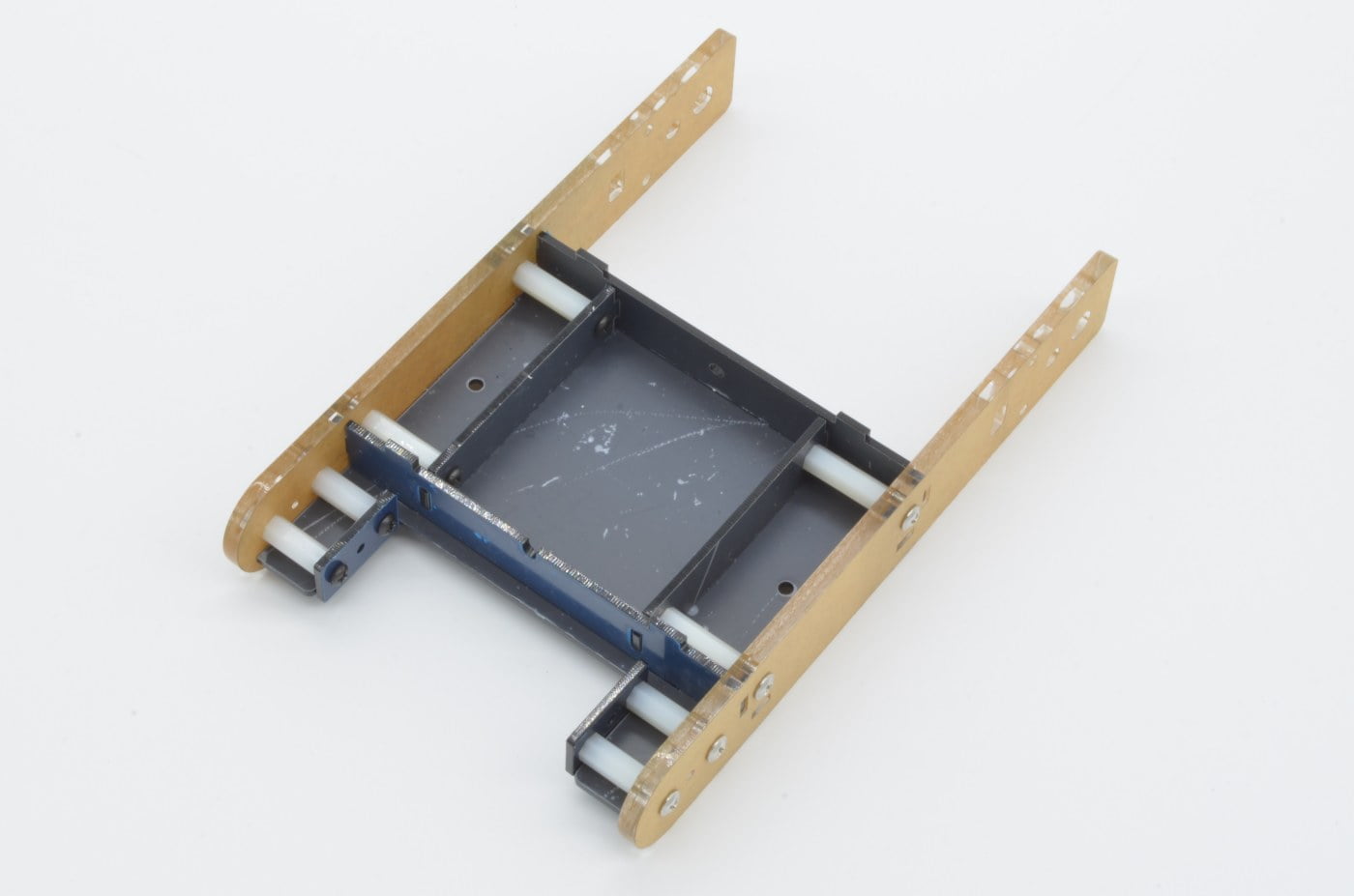
Next, we will start adding the structure to support the idler wheels of the tank tracks. These use standoffs, screws and brackets to provide a stable mounting point for the idler wheel shafts.
Start by finding 4 x 15mm standoffs and 4 x Silver M3 screws
The screws are attached through the outside, with the standoffs on the inside edges as shown in the image. In the next step we will attach the backing plate.
70%
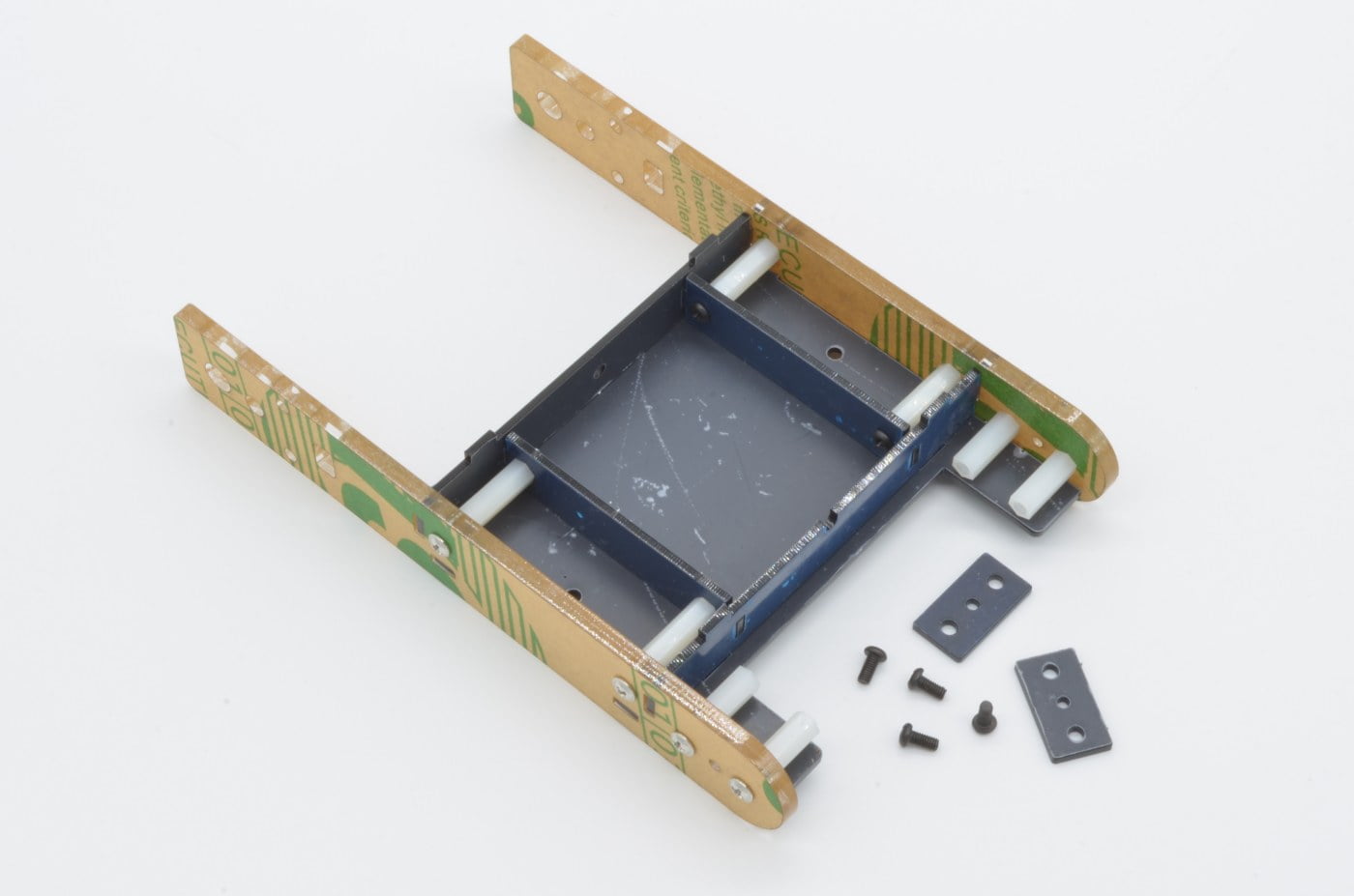
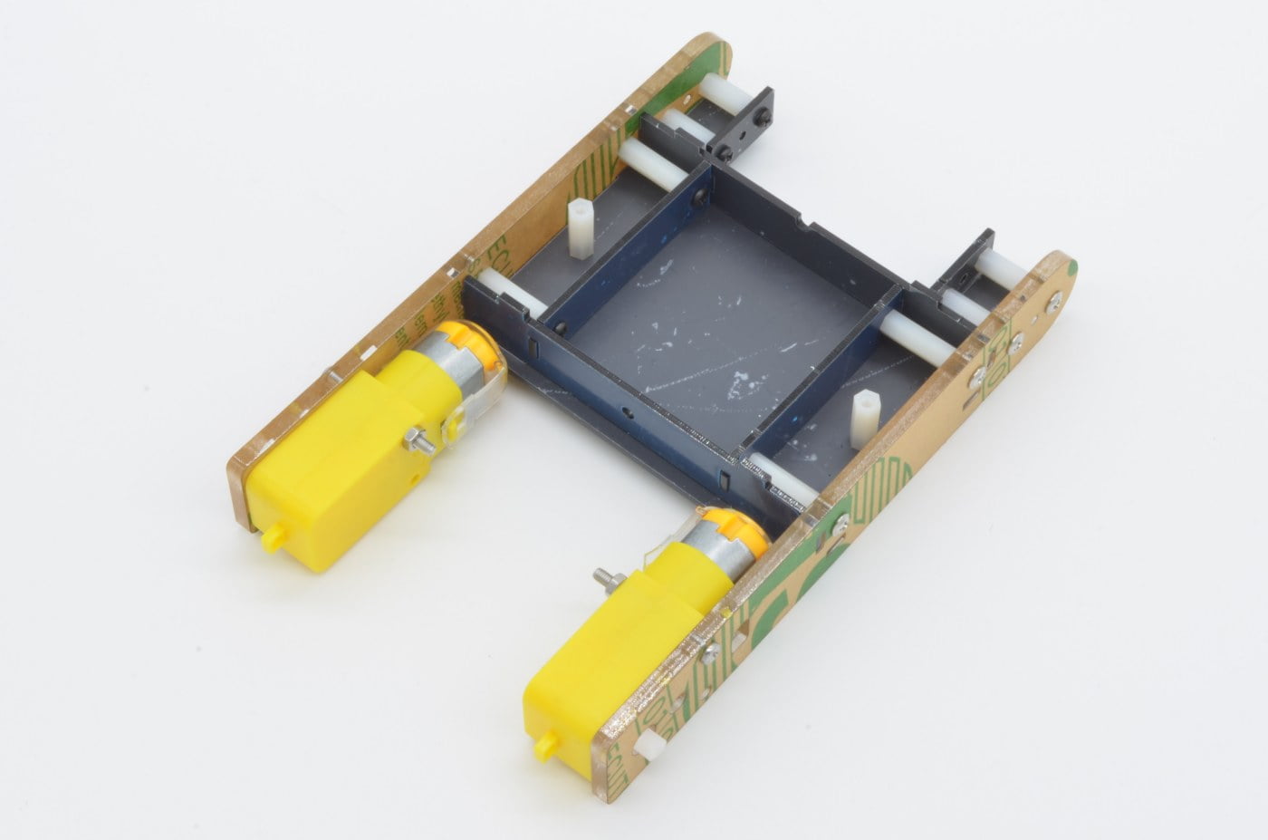
Step 5 - Idler Wheel Brackets (Continued)
The other half of the idler wheel mount is a small laser cut rectangle. Find four black screws and the two small plastic rectangles. These will fit flush against the base and standoffs.
The final assembly should look as seen in the photo. Next we will add motors and wheels!
50%
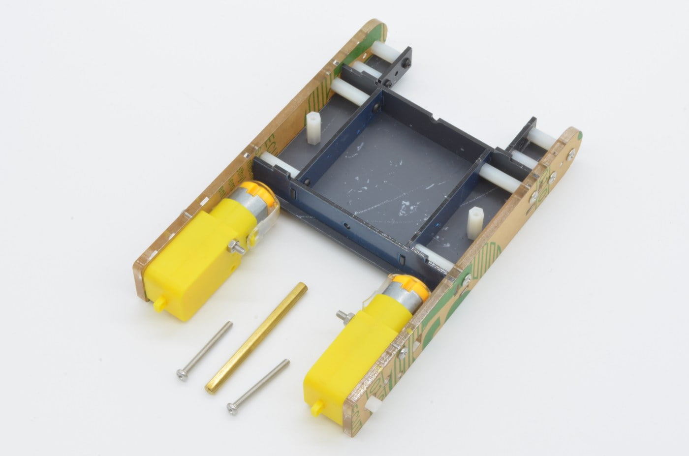
Step 6 - Adding The Motors
The motors are attached to the chassis using two screw points. We are going to start by attaching the top screw to each motor. Find 2 x 30mm screws and 2 x M3 nuts.
Note: Depending on your application, you may want to solder wires to your motors before installing them to the chassis. The tabs can be a little harder to access once installed.
The output shaft from the motor will fit through the outer structure. To prevent the wheel from catching on the extra screw threads, push the screws from the outside of the chassis towards the middle (so the nut is on the inside).
60%
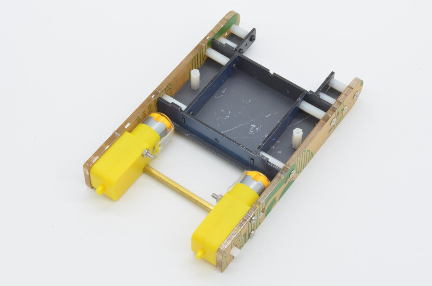
Step 7 - Lower Motor Brace
To help keep the chassis rigid, a large brass standoff is used between the two motors. It is threaded between the two lower motor mount screws. Find the last 2 x 30mm screws and the large standoff.
Line the standoff up with the motor mount holes and carefully thread the screws into the standoff. Once they are tightened down, the chassis will be a lot more ridged!
70%
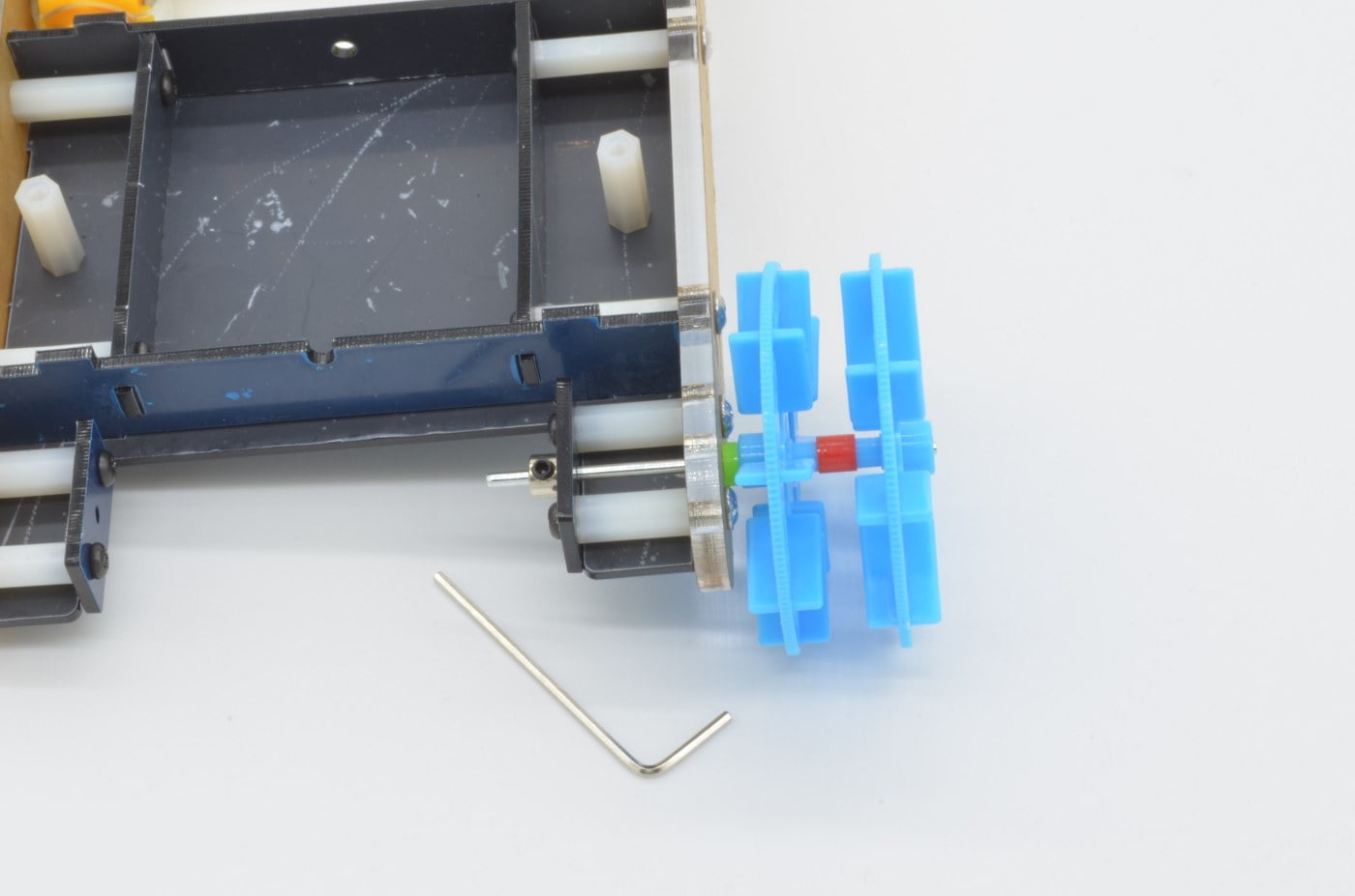
Step 8 - Idler Wheels
The idler wheels free-wheel at the opposite end of the track as the drive motors. These are the two wheels with long shafts. Find the two wheels with long shafts, the two green spacers, and the two slugs with set screws. We will also need the Allen key to tighten the two set screws.
Slide the green plastic spacer onto the shaft and then slide the whole assembly through the chassis wheel mount. The slug can then be installed, and tightened on the shaft. This should be fairly tight against the chassis, but loose enough for the axle to spin freely.
80%
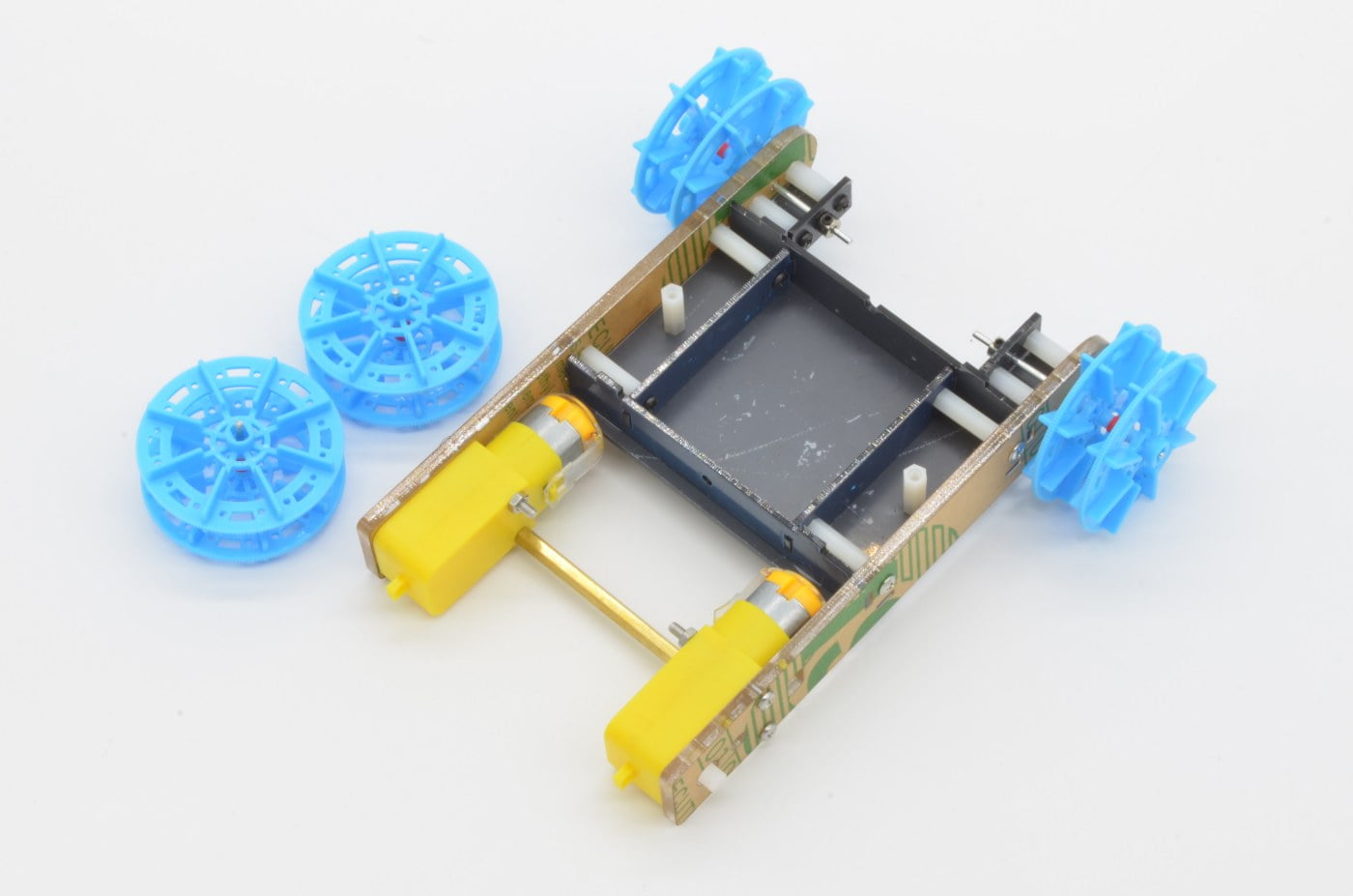
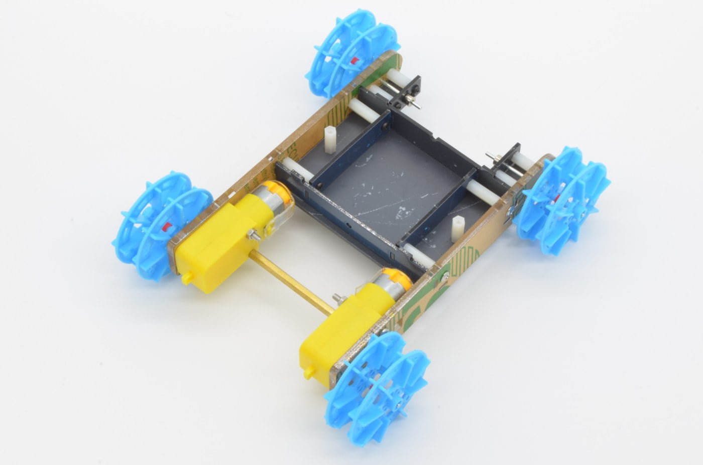
Step 9 - Drive Wheels & Tracks
Next we need to install the drive wheels to the motors. These are the two wheels with the short shafts.
Line the wheel short shafts up with the keyed motor output shaft. The shaft will line up with the motor’s flatted output. Once aligned correctly, press fit the wheels. Do not install these too tightly, as the motor mount screws will impact the wheels.
Next, we can install the tracks. These can be carefully stretched over the wheels and aligned with the guideway.
90%
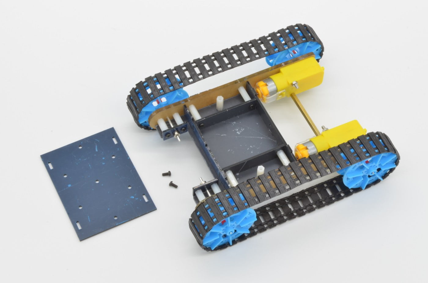
Step 10 - Cover Plate
Finally we can install the last cover plate. This plate finishes the internal structure of the chassis. Inside the panel there is room for electronics or a small battery pack. There are 5 mounting holes that can also be used to anchor a larger plate or mount electronics on the outside of the chassis.
The panel is secured using 2 x Black Screws. These thread into the standoffs inside the chassis.
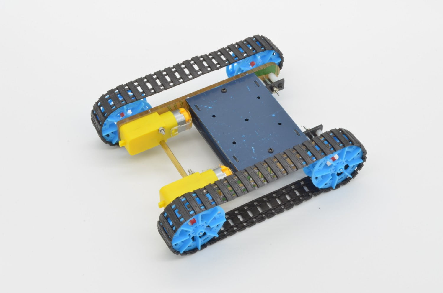
And with that last plate installed, the chassis is complete! Now add the motor controller and microcontroller of your choice and you are well on your way to a tracked robot!
Going forwards, many aspects of the chassis can be upgraded. The TT style motors are easily upgraded to a version compatible with wheel encoders, or even metal gears for added strength. The chassis can be expanded to provide more build space. Of course, sensors can be mounted all over to provide data about its surroundings.
100%
2 thoughts on “Tank Track Chassis Assembly Guide”
Mark Edwards
Step 6 shows parts on the chassis to f attach the lid (step 10), but there are no instructions telling you to install them.
– All the plastic and acrylic parts are covered with protective film. If you peel everything off before starting, you get a shiny black core with transparent sides.
– Step 5 goes before 4. I assembled mine using the supplied tools and the screwdriver was too long for step 5 after step 4, so I had to undo 4, do 5, and then redo 4.

2 thoughts on “Tank Track Chassis Assembly Guide”
Mark Edwards
Step 6 shows parts on the chassis to f attach the lid (step 10), but there are no instructions telling you to install them.
xsm
– All the plastic and acrylic parts are covered with protective film. If you peel everything off before starting, you get a shiny black core with transparent sides.
– Step 5 goes before 4. I assembled mine using the supplied tools and the screwdriver was too long for step 5 after step 4, so I had to undo 4, do 5, and then redo 4.