BC Robotics
Browse categories
- New Additions
- Shop
- On Sale / Clearance
- Popular Categories
- ArduinoArduino is the most popular open source microcontroller platform on the market. These easy to program devices can read sensors, control relays, light up LEDs, and even talk to one another. Their ability to interact with the real world by way of sensors and other electronics makes them ideal for automation such as watering a plant when it is dry, reading the weather, or controlling lights when it gets dark – the possibilities are endless. We carry a variety of Arduino compatible microcontrollers from several manufacturers, each with their own specific strengths and purposes. To further specialize your microcontroller, we carry a large selection of daughter boards (shields) which can add powerful sensors, GPS, or even LCD screens to your project! Just getting started with microcontrollers? We carry a variety of Arduino starter kits to get you reading sensors and blinking lights as easily as quickly as possible!
- BBC micro:bitThe BBC micro:bit is a pocket-sized computer designed for beginners in electronics and coding. The micro:bit makes getting into these often daunting fields as easy as possible. Programming the micro:bit V2 can be done by computer or by their intuitive app available for Android and iOS devices. Code can be designed using a drag and drop interface in the Blocks editor, Javascript, or Python.
- ESP8266 & ESP32The ESP8266 and ESP32 microcontrollers from Espressif are powerful, inexpensive, and feature integrated WiFi connectivity. These are ideal for IoT applications. We offer a variety of different ESP8266 and ESP32 modules for different skill levels.
- FeatherFeather is a flexible and powerful family of microcontroller main-boards (Feathers) and daughter-boards (Wings) designed with portability in mind. All Feathers have integrated battery connectors (and most have built in lipo chargers) The Feather form factor is not locked to a specific chipset or programming language. Feathers are available with a variety of chipsets and on-board features. Most Feathers and FeatherWings have example code and libraries written in Arduino C/C++ and CircuitPython.
- Makey MakeyThe Makey Makey kit is a electronics kit designed for beginners. It explores the concepts of creating circuits through everyday items. When plugged into a computer you can use the Makey Makey to make anything into a keyboard or mouse. No programming required! Projects like a Banana Drum Set, Cat Detector, Musical Stairs, and countless others are easier than you think! We carry the Makey Makey Classic Kit – a starter kit for the Makey Makey – along with extra alligator clips, copper conductive tape, and replacement cables.
- Raspberry PiThe Raspberry Pi was first introduced in early 2012 as a simple, low cost, computer fit onto a circuit board roughly the size of a credit card. The idea was to use this low cost computer to promote teaching of computer science in schools but it has grown to be so much more! Since its release, well over 30 million of these little computers have been sold. We have carried the Raspberry Pi in Canada since it first became available and have watched as the Pi has morphed into a complete development platform with powerful single-board computers, cameras, touchscreens, and other accessories. Its multitude of inputs and outputs for electronics and computer peripherals and its impressive computing power mean it can be used to make just about anything you can imagine. The newest and most powerful version, the Raspberry Pi 4, is now available!
- Popular Brands
- AdafruitAdafruit was founded in 2005 by MIT engineer, Limor “Ladyada” Fried. Her goal was to create the best place online for learning electronics and making the best designed products for makers of all ages and skill levels. In the last 10 years, Adafruit has grown to over 100+ employees in the heart of NYC with a 50,000+ sq ft. factory.
- ArduinoArduino is an ever growing platform used by some of the most popular microcontrollers out there. For many of us, this is where it all started – the Arduino was (and still is today) a pioneer when it comes to making programming hardware easy and accessible. We have one of the largest selections of Arduino and Arduino accessories in Canada. These range from basic Arduino Uno, to Cellular and WiFi connected devices perfect for the Internet of Things, and all the accessories needed to get them running!
- Micro:bitMicro:bit Educational Foundation are the manufacturers of the popular BBC micro:bit; a pocket-sized computer designed for beginners in electronics and coding. The micro:bit makes getting into these often daunting fields as easy as possible. Programming the micro:bit V2 can be done by computer or by their intuitive app available for Android and iOS devices. Code can be designed using a drag and drop interface in the Blocks editor, Javascript, or Python.
- BC RoboticsIn addition to stocking 2000+ unique items, we also manufacture our own accessories right here at BC Robotics. In 2014 we began developing our own widgets and add-ons for Arduino, Raspberry Pi, and general prototyping. This has now grown to over 80 different SKUs. Our boards are assembled in-house with top quality components. Many feature detailed tutorials or project guides to get you up and running as quickly as possible!
- Raspberry Pi
- SparkFunSince 2003, SparkFun has been helping turn ideas into reality – whether you’re creating a smart weather station, exploring the frontier of machine learning, building a robot for school or prototyping your first (or tenth) product. No matter your vision or skill level, our open source components, resources and online tutorials are designed to broaden access to innovative technology and make the road to a finished project shorter. We’re here to help you start something.
- Frequently Asked Questions
- My Account
- Wishlist
- Cart
Free Shipping - US & Canada @ $150 CAD
Raspberry Pi Weather Station – Part 2
PRODUCT TUTORIAL
- Chris @ BCR
- July 12, 2018
- 12:00 pm
- 129 Comments
In the last part of this tutorial we added our components to the weather board and connected everything up. Now that we have everything ready for power, we can work on the software / coding side of this project. In part two of this tutorial we will boot up the Raspberry Pi, do some initial configuration of the Raspbian operating system, install Python libraries for a few of the sensors, and write some basic Python code to collect and display data from each of the sensors. The Python code will be quite long, but we have broken it down into smaller steps. As always, if you have any questions, feel free to post at the bottom of the page.
Operating System:
Before we get started, you should have a microSD card pre-installed with Raspbian. We are using the installation image dated June 27, 2018. Using a different version than this *could* require additional steps during the installation process – so for this reason we recommend using the exact version we are. At the time of writing this tutorial, this is the most current version available from the Raspberry Pi Foundation and it can be found here.
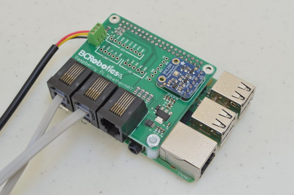
The Parts Needed:
In addition the completed assembly from Part 1, this tutorial will be requiring a few additional parts:


A few other things will also be needed for this tutorial:
- A USB Keyboard & Mouse
- A HDMI Compatible Monitor
- Internet Access
Step 1 – Boot Up
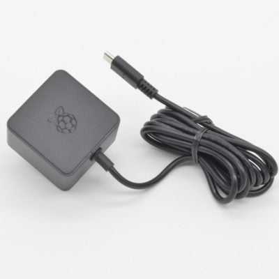
We are going to start by inserting the microSD card with our operating system pre-installed into the Pi. Your keyboard, mouse and monitor should also be connected at this time. Power up the Pi by plugging in the Power Supply. Once the Pi has done its initial boot of the operating system you should arrive at a desktop. A dialogue should appear for initial configuration – we will take care of this in the next step.
5.2%
Step 2 – OS Configuration
As of this version of Raspbian, most initial setup can be done by following the dialogue that pops up on first boot up. However, we do need to set up a few additional things once this is initial configuration is completed. Follow through the initial setup, if prompted to reboot – go ahead and do that as well.
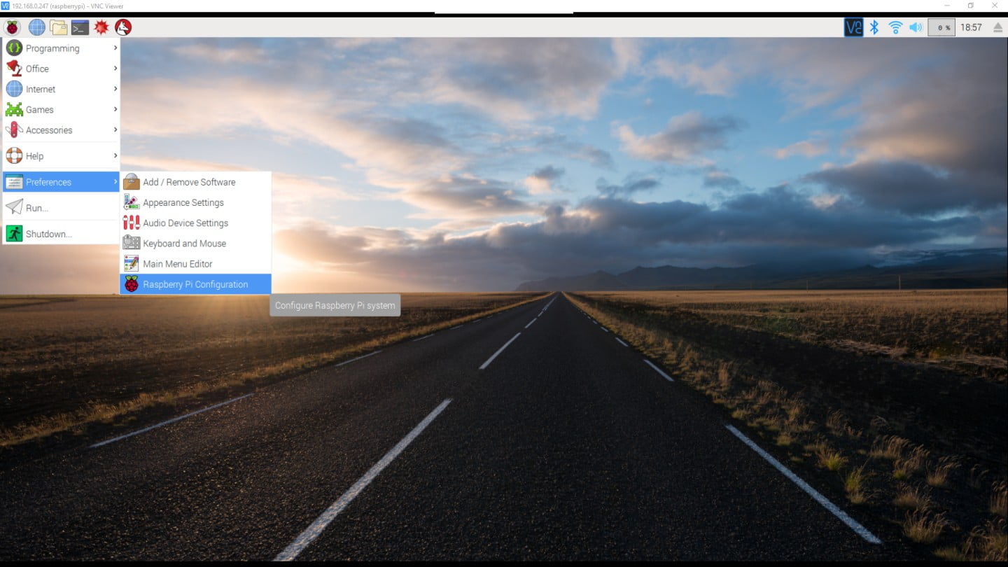
Once all of that has been completed, we can go ahead and configure a few more things. Click the Raspberry Logo in the top left corner, scroll down to Preferences, and select “Raspberry Pi Configuration”.
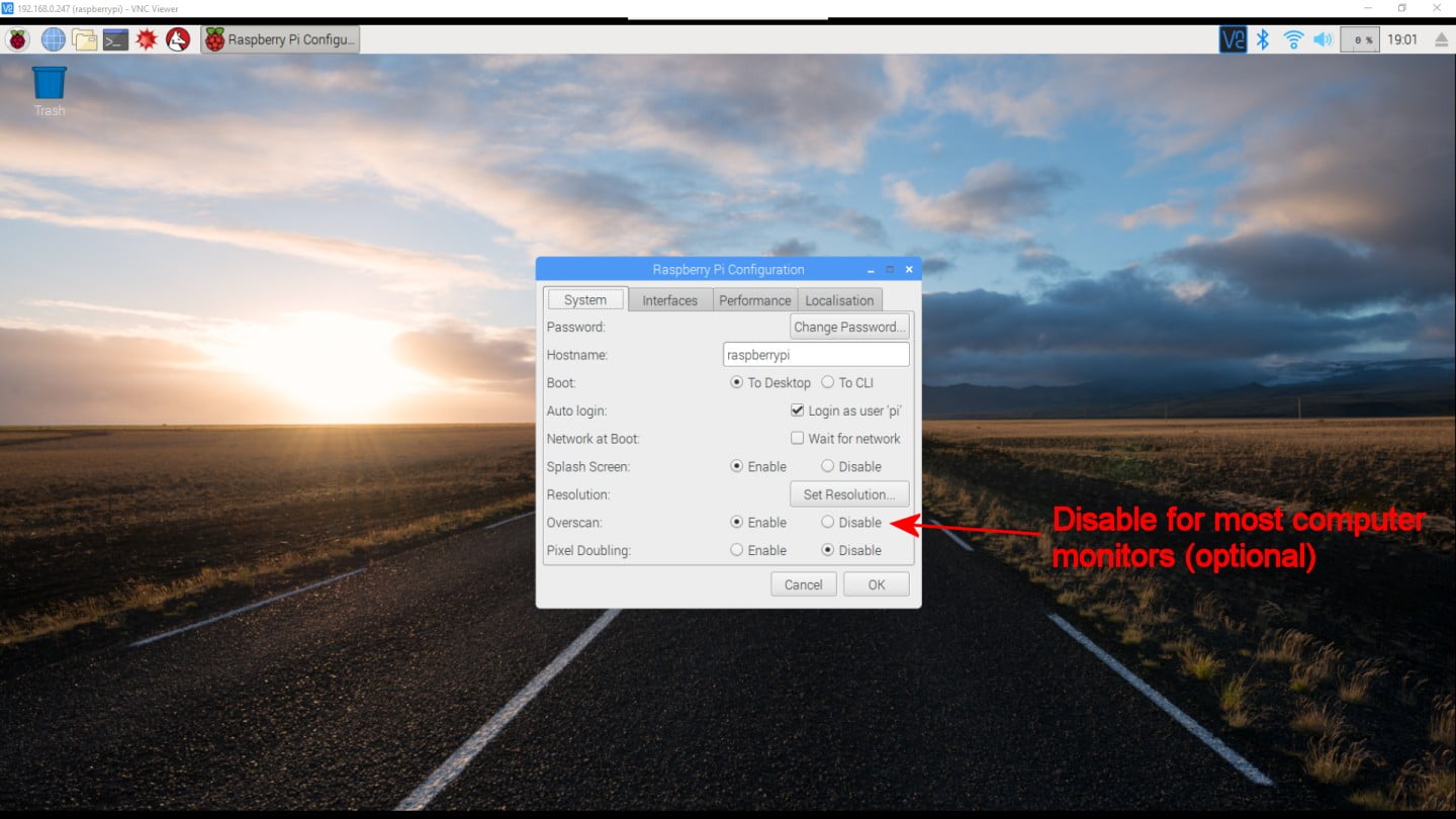
On the first tab you can change your overscan settings. If you are using a computer monitor, you may want to disable the overscan setting to remove the black bars on the sides of the screen.
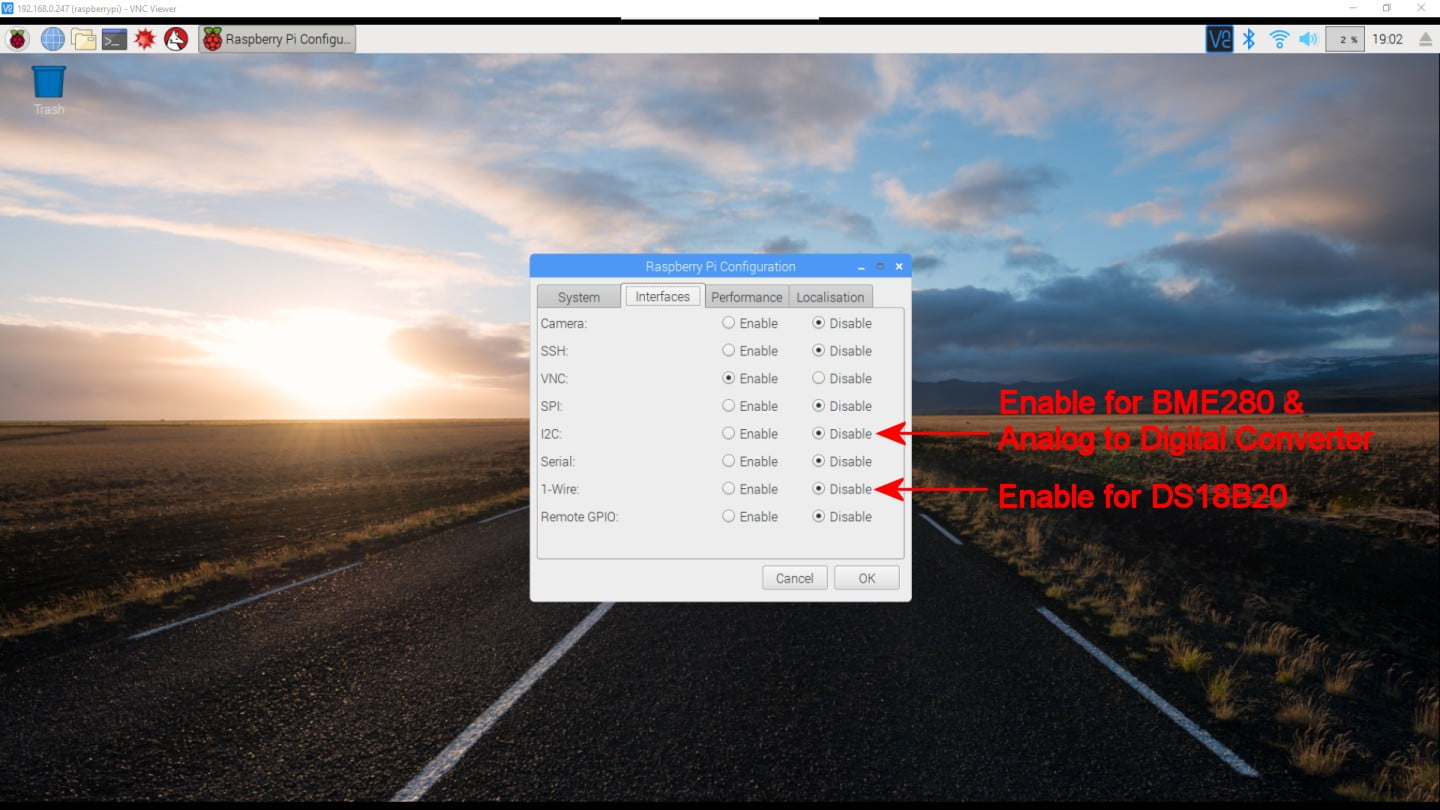
On the second tab we are going to want to enable the I2C and 1-Wire interfaces. These are the two interfaces our sensors are using in this project.
If prompted to reboot, click yes. Once the Pi boots back up we can proceed.
10.4%
Step 3 – Internet Connectivity

Before we can install any of the libraries or make any of the sensors work we need internet connectivity. If you are using WiFi, this was probably already set up during the initial configuration. If it isn’t working, or you skipped that step, it can be accessed by clicking the connectivity logo (located beside the Volume control in the top right corner of the screen).
Ethernet is as simple as plugging it into the Pi – if you are planning to use ethernet, go ahead and plug this in if you haven’t already.
15.6%
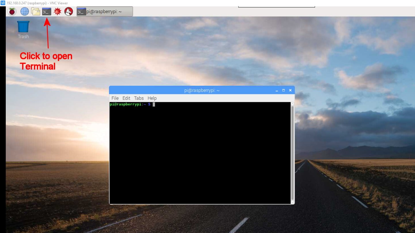
Step 4 – Terminal
Now that all of the basic configuration is done, we can get on with installing the software libraries needed to read each of the sensors. These libraries of code are going to take a lot of the hard work out of reading the sensors. We are going to install these using the “Terminal” , in the bar at the top of the screen, click the black square logo, and this window should pop up:
20.8%
Step 5 – Adafruit Python GPIO Library
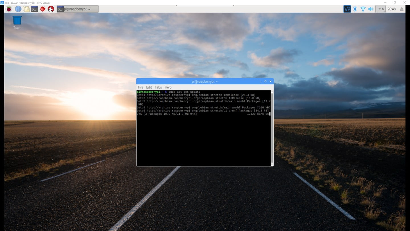
The first item to install is the Adafruit Python GPIO Library. This package is the basis for several others that we will be using. To install it we will type a series of commands into the terminal window we just opened up.
Run each of these commands (in order!) by typing them in and hitting enter:
sudo apt-get update
sudo pip3 install --upgrade setuptools
pip3 install RPI.GPIO
pip3 install adafruit-blinka
26%
Step 6 – Adafruit BME280 Library
Next we will install the Adafruit BME280 library for Python. This library was also created by Adafruit and has been designed to work with their BME280 Temperature/Humidity/Pressure sensor breakout board.
Run the following command in the terminal:
sudo pip3 install adafruit-circuitpython-bme280
31.2%
Step 7 – ADS1x15 Library
Next, we are going to set up the ADS1015 Analog to Digital chip. Adafruit has built an easy to use library for this series of Analog to Digital converters. We will use this to read the wind direction. To install the library, type the following command into the Terminal:
sudo pip3 install adafruit-circuitpython-ads1x15
36.4%
Step 8 – DS18B20
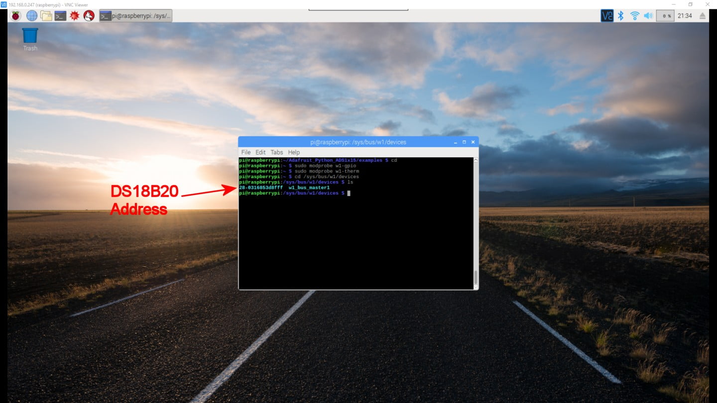
Now it is time to set up the DS18B20 temperature sensor. The setup for this sensor is a bit different; the past two sensors both used the I2C bus, the DS18B20 uses 1-Wire. Enter the following commands in the terminal:
					cd
sudo modprobe w1-gpio
sudo modprobe w1-therm
cd /sys/bus/w1/devices
ls
Since the temperature sensor will be listed in the devices folder, we will want to see everything in that folder. The last command “ls” will display the contents of the folder in the window. Our DS18B20 shows up with an address of 28-0316853d8fff – but each sensor has a unique ID so your number will not match the image!
41.6%
Step 9 – Test Your DS18B20
Time to get a reading from the DS18B20 sensor! Enter the following command with your sensor ID in place of *sensor ID*
cd *sensor ID*
Now we can pull a temperature from it by entering the following command:
cat w1_slave
Not as easy to read as the BME280, but the information should be there. The temperature is located in the second line, take the number given and divide by 1000 to get the temperature in degrees Celsius.
46.8%
Step 10 – DS18B20 Library
Since the DS18B20 isn’t the easiest sensor to read directly in Python, we will be installing one last library to make it a little more straight forward. In the terminal type the following commands:
					cd
sudo pip3 install w1thermsensor
This will make things quite a bit easier once we start writing some code.
52%
Step 11 – Python
idle3 & newer OS Versions
By default, the idle development environment is not included with Raspberry Pi installations in newer OS versions. It can be installed or an alternate development environment can be used.
Now we are getting somewhere! All of the complex sensors are sending back data so lets write some basic python code to poll each of the sensors and report back every 15 seconds. We aren’t going for award winning code here, just something easy to understand for those relatively new to Python.
We want to program in Python 3 so type the following command in the terminal and hit enter:
idle3
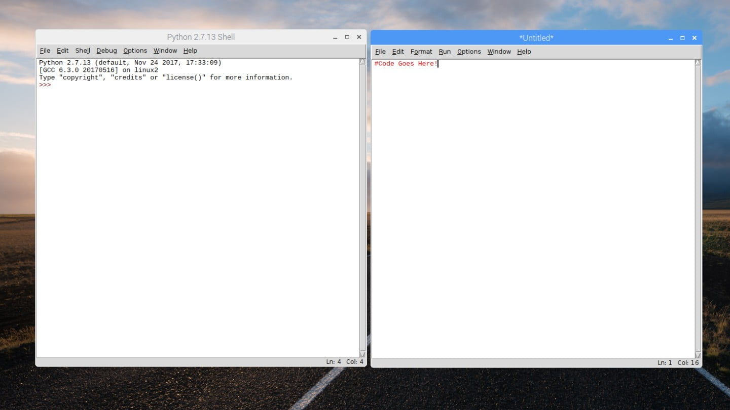
Alternatively, Python 3 can be found by clicking the Raspberry Button in the top left. Under programming you will find a shortcut. Either way, A new window should have opened for the Python 3 Shell. We are now done with the terminal window so it can be minimized or moved out of the way (but don’t close it!).
57.2%
Step 12 – Getting Ready
In the Python Shell window we just opened, click “File” and “New File” to start a new Python file. This will open another window that we will write all of our code in.
There are a million different ways to approach writing code to accomplish our end result of collecting data from sensors and sending it to Thinkspeak. We are going to approach this by basing the code around the timing interval we want to send data to Thingspeak (once every 15 seconds). This allows us to structure the program around a simple 15 second time loop.
Why 15 seconds? Two reasons: We want to have sufficient time to measure a wind speed (there are ways to manage this at issue, but we want to keep this as simple as possible) and Thingspeak limits free accounts to a once per 15 second data rate.
62.4%
Step 13 – Starting The Code
Before we can read any of the sensors, we will need to create the basic framework of the program. This means we need to import the time library, create our loop, and set the interval we want to pause the code each time the loop has completed. For those unfamiliar with Python, note that the white spaces (tabs and spaces) are very important in this language so be sure to format exactly as shown in the example.
					import time

interval = 15 #How long we want to wait between loops (seconds)

while True:

    time.sleep(interval)
Libraries are added to the project using the import command. On the first line we are importing the time library. On line 3 we define a variable to store the length of time in seconds that we want to sleep the program during each loop of the code. Next, we want to create the loop itself – in Python this can be done in a variety of ways; “While true:” works well. Note that when you press “Enter” the next line becomes indented. Finally, on line 7 we “sleep” or pause our program using the variable we set above.
Note: Because we are going to be adding a lot of code over the next few steps, each new line we add will be highlighted in the example code and the line number will correspond to notes below the code.
67.6%
Step 14 – Read The Temperature
During the set up we installed a bunch of libraries to make this program a lot easier to write. We are going to use one of these libraries right now to read the DS18B20 temperature sensor. In these next bits of code we are going to import the DS18B20 library, set up the sensor, read the sensor, and print the result.
					import time
from w1thermsensor import W1ThermSensor

ds18b20 = W1ThermSensor()

interval = 15 #How long we want to wait between loops (seconds)

while True:

    time.sleep(interval)

    #Pull Temperature from DS18B20
    temperature = ds18b20.get_temperature()

    #Print the results
    print( "Temperature: " , temperature)
- (2) Similar to the time library, we import the w1Thermsensor library
- (4) Next we create our temperature sensor object and give it a name
- (13) Down in the loop we get the temperature from the sensor and store it in a variable named “temperature”
- (16) And finally print the result using the print command
Let’s try it out – press “F5” and it should prompt you to save it. After saving it should run, and in the Python Shell window you should see the temperature appear after a 15 second wait. It will continue to post an updated temperature every 15 seconds. This can be stopped by pressing “Ctrl + C”.
72.8%
Step 15 – Read The BME280
Next we will tackle the BME280 – this provides us with three measurements: Temperature, Pressure, and Humidity. The library we have installed already handles most of the hard work, but because of the way this library is written there are a few tricks that will prevent issues going forwards.
Just like the last sensor, we will import the library, set up the sensor, read the sensor, and print the results. Since we are now using the Circuit Python compatible libraries in this tutorial, there are a few extra chunks of code to add.
					import time
from w1thermsensor import W1ThermSensor

import board
import busio
from adafruit_bme280 import basic as adafruit_bme280
i2c = busio.I2C(board.SCL, board.SDA)

bme = adafruit_bme280.Adafruit_BME280_I2C(i2c)

ds18b20 = W1ThermSensor()

interval = 15 #How long we want to wait between loops (seconds)

while True:

    time.sleep(interval)

    #Pull Temperature from DS18B20
    temperature = ds18b20.get_temperature()


    #Pull temperature from BME280
    case_temp = bme.temperature

    #Pull pressure from BME280 Sensor & convert to kPa
    pressure_pa = bme.pressure
    pressure = pressure_pa / 10

    #Pull humidity from BME280
    humidity = bme.humidity

    #Print the results
    print( "Temperature: " , temperature)
    print( "Humidity: " , humidity, "%")
    print( "Pressure: " , pressure, "kPa")
    print( " ")
- (4) Import the board library from Adafruit Blinka
- (5) Import the busio library from Adafruit Blinka
- (6) Import the Adafruit BME280 library
- (7) Configure I2C to use the boards hardware I2C pins
- (9) Next we create our BME280 sensor object and give it a name. In the brackets we set it to I2C, as that is how it is connected
- (24) Get the temperature from the BME280 and store it in the variable “case_temp”
- (27) Get the pressure from the BME280 and store it in the variable “pressure_pa”
- (28) Since we want kilopascals, we will divide by 10. The new result is stored in the variable “pressure”
- (31) Get the humidity from the BME280 and store it in the variable “humidity”
- (35) Print the humidity
- (36) Print the pressure
- (37) Print a blank line to separate the data and make it easier to read
Although we are not using the BME’s temperature sensor, we still need to read it. Because of the way the library is written, simply asking for the pressure and humidity without asking for the temperature first will cause your program to crash. So we have read the temperature and called it “case temp” as it would be a decent indication of the air temperature inside the box that this will eventually end up in.
Once your code looks like the above, hit “F5” again to run it. This time there should be a bunch more information!
78%
Step 16 – Read The ADC (Wind Direction)
Wind direction is next – again we are going to import the library, set up the sensor, and read the results. Unlike all of the past sensors, this one does not simply spit out exactly what we want to know. The sensor has differing resistance for each of the 16 wind directions it is capable of monitoring – in its current configuration, this means each direction will output a different voltage. We will read this voltage with our Analog to Digital converter and convert this to useable information in the form of a direction.
					import time
from w1thermsensor import W1ThermSensor

import board
import busio
from adafruit_bme280 import basic as adafruit_bme280
i2c = busio.I2C(board.SCL, board.SDA)

import adafruit_ads1x15.ads1015 as ADS
from adafruit_ads1x15.analog_in import AnalogIn

bme = adafruit_bme280.Adafruit_BME280_I2C(i2c)
ads = ADS.ADS1015(i2c)
ads.gain = 1

ds18b20 = W1ThermSensor()

interval = 15 #How long we want to wait between loops (seconds)

while True:

    time.sleep(interval)

    #Pull Temperature from DS18B20
    temperature = ds18b20.get_temperature()

    #Pull temperature from BME280
    case_temp = bme.temperature

    #Pull pressure from BME280 Sensor & convert to kPa
    pressure_pa = bme.pressure
    pressure = pressure_pa / 10

    #Pull humidity from BME280
    humidity = bme.humidity

    #Calculate wind direction based on ADC reading
    chan = AnalogIn(ads, ADS.P0)
    val = chan.value
    windDir = "Not Connected"
    windDeg = 999

    if 20000 <= val <= 20500:
        windDir = "N"
        windDeg = 0

    if 10000 <= val <= 10500:
        windDir = "NNE"
        windDeg = 22.5

    if 11500 <= val <= 12000:
        windDir = "NE"
        windDeg = 45

    if 2000 <= val <= 2250:
        windDir = "ENE"
        windDeg = 67.5

    if 2300 <= val <= 2500:
        windDir = "E"
        windDeg = 90

    if 1500 <= val <= 1950:
        windDir = "ESE"
        windDeg = 112.5

    if 4500 <= val <= 4900:
        windDir = "SE"
        windDeg = 135

    if 3000 <= val <= 3500:
        windDir = "SSE"
        windDeg = 157.5

    if 7000 <= val <= 7500:
        windDir = "S"
        windDeg = 180

    if 6000 <= val <= 6500:
        windDir = "SSW"
        windDeg = 202.5

    if 16000 <= val <= 16500:
        windDir = "SW"
        windDeg = 225

    if 15000 <= val <= 15500:
        windDir = "WSW"
        windDeg = 247.5

    if 24000 <= val <= 24500:
        windDir = "W"
        windDeg = 270

    if 21000 <= val <= 21500:
        windDir = "WNW"
        windDeg = 292.5

    if 22500 <= val <= 23000:
        windDir = "NW"
        windDeg = 315

    if 17500 <= val <= 18500:
        windDir = "NNW"
        windDeg = 337.5

    #Print the results
    print( "Temperature: " , temperature)
    print( "Humidity: " , humidity, "%")
    print( "Pressure: " , pressure, "kPa")
    print( "Wind Dir: " , windDir, " (", windDeg, ")")
    print( " ")
- (9) Just like the other libraries, we import the Adafruit_ADS1x15 library
- (10) Load the AnalogIn library for the ADS1x15
- (13) Next we create our ADC object and give it a name. It is also connected over I2C
- (14) Set the programmable gain amplifier to 1 in the ADC
- (38) Get the reading from the ADC channel 0 and store it in the variable “chan”
- (39) We only need the adc value, so pull that from chan and assign it to a new variable “val” after multiplying it by 16. This is required due to changes in the Adafruit Library.
- (40-41) Define a base level reading if sensor isn’t connected
- (43-105) Check to see if val is between two values, if it is we assign the direction, otherwise it continues down the list until a match is found
- (111) Print the results
The code for this is large and cumbersome, but rather than slim it down to something elegant and easy to type, we would rather show the mental process of how to figure out what direction the wind is coming from. Each direction outputs a different number – but this number will change a small amount based on temperature, power fluctuations, etc. so we cant just check if our ADC output matches a number in a list. Instead we have to see if they fall within a range.
So where do each of the ranges of numbers come from that we are testing against? The numbers we are using were found by manually moving the wind direction sensor to each of the directions and reading the output. These numbers were written down and then we added a buffer to each “side” to ensure we don’t have any incorrect readings. So as long as the value from the ADC is between these large ranges, it will read that specific direction. Feel free to test the code again with the “F5” key.
83.2%
Step 17 – Wind Speed
The last two sensors are simple digital inputs on the Pi, these do not have a fancy chip to read or anything of the sort. The wind speed sensor is effectively a magnet and a small magnetic switch. As the sensor spins the magnet moves past a switch, causing it to close. A wind speed of 1.2km/h will cause this switch to open or close once per second. So we just need to count how many times it is opening and closing per second to figure out a speed.
The Pi has an easy way of monitoring this sort of thing. Even though we have paused the entire program for a period of 15 seconds, we can create a background process that will still watch for changes in this pin and keep count while the main code is paused.
So lets get started: First we need to import the Raspberry Pi GPIO library, set up the pin we are using, and create the background process that monitors the pin. We will then calculate the windspeed and, finally, print the result.
					import time
from w1thermsensor import W1ThermSensor

import board
import busio
from adafruit_bme280 import basic as adafruit_bme280
i2c = busio.I2C(board.SCL, board.SDA)

import adafruit_ads1x15.ads1015 as ADS
from adafruit_ads1x15.analog_in import AnalogIn

import RPi.GPIO as GPIO

bme = adafruit_bme280.Adafruit_BME280_I2C(i2c)
ads = ADS.ADS1015(i2c)
ads.gain = 1

ds18b20 = W1ThermSensor()

interval = 15 #How long we want to wait between loops (seconds)
windTick = 0 #Used to count the number of times the wind speed input is triggered

#Set GPIO pins to use BCM pin numbers
GPIO.setmode(GPIO.BCM)

#Set digital pin 17 to an input and enable the pullup
GPIO.setup(17, GPIO.IN, pull_up_down=GPIO.PUD_UP)

#Event to detect wind (4 ticks per revolution)
GPIO.add_event_detect(17, GPIO.BOTH)
def windtrig(self):
    global windTick
    windTick += 1

GPIO.add_event_callback(17, windtrig)

while True:

    time.sleep(interval)

    #Pull Temperature from DS18B20
    temperature = ds18b20.get_temperature()

    #Pull temperature from BME280
    case_temp = bme.temperature

    #Pull pressure from BME280 Sensor & convert to kPa
    pressure_pa = bme.pressure
    pressure = pressure_pa / 10

    #Pull humidity from BME280
    humidity = bme.humidity

    #Calculate wind direction based on ADC reading
    chan = AnalogIn(ads, ADS.P0)
    val = chan.value
    windDir = "Not Connected"
    windDeg = 999

    if 20000 <= val <= 20500:
        windDir = "N"
        windDeg = 0

    if 10000 <= val <= 10500:
        windDir = "NNE"
        windDeg = 22.5

    if 11500 <= val <= 12000:
        windDir = "NE"
        windDeg = 45

    if 2000 <= val <= 2250:
        windDir = "ENE"
        windDeg = 67.5

    if 2300 <= val <= 2500:
        windDir = "E"
        windDeg = 90

    if 1500 <= val <= 1950:
        windDir = "ESE"
        windDeg = 112.5

    if 4500 <= val <= 4900:
        windDir = "SE"
        windDeg = 135

    if 3000 <= val <= 3500:
        windDir = "SSE"
        windDeg = 157.5

    if 7000 <= val <= 7500:
        windDir = "S"
        windDeg = 180

    if 6000 <= val <= 6500:
        windDir = "SSW"
        windDeg = 202.5

    if 16000 <= val <= 16500:
        windDir = "SW"
        windDeg = 225

    if 15000 <= val <= 15500:
        windDir = "WSW"
        windDeg = 247.5

    if 24000 <= val <= 24500:
        windDir = "W"
        windDeg = 270

    if 21000 <= val <= 21500:
        windDir = "WNW"
        windDeg = 292.5

    if 22500 <= val <= 23000:
        windDir = "NW"
        windDeg = 315

    if 17500 <= val <= 18500:
        windDir = "NNW"
        windDeg = 337.5

    #Calculate average windspeed over the last 15 seconds
    windSpeed = (windTick * 1.2) / interval
    windTick = 0

    #Print the results
    print( "Temperature: " , temperature)
    print( "Humidity: " , humidity, "%")
    print( "Pressure: " , pressure, "kPa")
    print( "Wind Dir: " , windDir, " (", windDeg, ")")
    print( "Wind Speed: " , windSpeed, "KPH")
    print( " ")
- (12) Just like the other libraries, we import the GPIO library.
- (21) Create a variable to store the number of times the wind sensor pin is triggered
- (24) Set the GPIO pins to use Broadcom’s pin numbering
- (27) Set pin 17 to be an input and enable the pullup
- (30-35) Create a background process to keep track of how many times pin 17 transitions from HIGH to LOW or LOW to HIGH, each time it does we add 1 to the count
- (125) Calculate the wind speed – 1.2km/h per tick per second. This will result in an average speed over the last 15 seconds
- (126) Reset our counter
- (133) Print the result
Once again, feel free to test the code again with the “F5” key. Spinning the wind speed sensor will result in an average speed over the last 15 seconds being printed every interval.
88.4%
Step 18 – Rainfall
Similar to the wind speed sensor, the rain gauge works with a magnet and a reed switch. Inside this sensor a small tipping device will switch back and forth every 0.2794mm of rain that falls. So we just need to count the number of times it switches back and forth and multiply to calculate the rainfall.
We are going to do this with another background process, similar to the one used for the wind speed sensor. Instead of counting transitions from high to low and low to high, this sensor requires we only count when the pin is falling from high to low to accurately capture the tipping gauge moving. For this reason we will set the event detect to “Falling”. Now it will ignore any change of low to high, and only increment our count when it goes from high to low.
					import time
from w1thermsensor import W1ThermSensor

import board
import busio
from adafruit_bme280 import basic as adafruit_bme280
i2c = busio.I2C(board.SCL, board.SDA)

import adafruit_ads1x15.ads1015 as ADS
from adafruit_ads1x15.analog_in import AnalogIn

import RPi.GPIO as GPIO

bme = adafruit_bme280.Adafruit_BME280_I2C(i2c)
ads = ADS.ADS1015(i2c)
ads.gain = 1

ds18b20 = W1ThermSensor()

interval = 15 #How long we want to wait between loops (seconds)
windTick = 0 #Used to count the number of times the wind speed input is triggered
rainTick = 0 #Used to count the number of times the rain input is triggered

#Set GPIO pins to use BCM pin numbers
GPIO.setmode(GPIO.BCM)

#Set digital pin 17 to an input and enable the pullup
GPIO.setup(17, GPIO.IN, pull_up_down=GPIO.PUD_UP)

#Set digital pin 23 to an input and enable the pullup
GPIO.setup(23, GPIO.IN, pull_up_down=GPIO.PUD_UP)

#Event to detect wind (4 ticks per revolution)
GPIO.add_event_detect(17, GPIO.BOTH)
def windtrig(self):
    global windTick
    windTick += 1

GPIO.add_event_callback(17, windtrig)

#Event to detect rainfall tick
GPIO.add_event_detect(23, GPIO.FALLING)
def raintrig(self):
    global rainTick
    rainTick += 1

GPIO.add_event_callback(23, raintrig)

while True:

    time.sleep(interval)

    #Pull Temperature from DS18B20
    temperature = ds18b20.get_temperature()

    #Pull temperature from BME280
    case_temp = bme.temperature

    #Pull pressure from BME280 Sensor & convert to kPa
    pressure_pa = bme.pressure
    pressure = pressure_pa / 10

    #Pull humidity from BME280
    humidity = bme.humidity

    #Calculate wind direction based on ADC reading
    chan = AnalogIn(ads, ADS.P0)
    val = chan.value
    windDir = "Not Connected"
    windDeg = 999

    if 20000 <= val <= 20500:
        windDir = "N"
        windDeg = 0

    if 10000 <= val <= 10500:
        windDir = "NNE"
        windDeg = 22.5

    if 11500 <= val <= 12000:
        windDir = "NE"
        windDeg = 45

    if 2000 <= val <= 2250:
        windDir = "ENE"
        windDeg = 67.5

    if 2300 <= val <= 2500:
        windDir = "E"
        windDeg = 90

    if 1500 <= val <= 1950:
        windDir = "ESE"
        windDeg = 112.5

    if 4500 <= val <= 4900:
        windDir = "SE"
        windDeg = 135

    if 3000 <= val <= 3500:
        windDir = "SSE"
        windDeg = 157.5

    if 7000 <= val <= 7500:
        windDir = "S"
        windDeg = 180

    if 6000 <= val <= 6500:
        windDir = "SSW"
        windDeg = 202.5

    if 16000 <= val <= 16500:
        windDir = "SW"
        windDeg = 225

    if 15000 <= val <= 15500:
        windDir = "WSW"
        windDeg = 247.5

    if 24000 <= val <= 24500:
        windDir = "W"
        windDeg = 270

    if 21000 <= val <= 21500:
        windDir = "WNW"
        windDeg = 292.5

    if 22500 <= val <= 23000:
        windDir = "NW"
        windDeg = 315

    if 17500 <= val <= 18500:
        windDir = "NNW"
        windDeg = 337.5

    #Calculate average windspeed over the last 15 seconds
    windSpeed = (windTick * 1.2) / interval
    windTick = 0

    #Calculate accumulated rainfall over the last 15 seconds
    rainFall = rainTick * 0.2794
    rainTick = 0

    #Print the results
    print( "Temperature: " , temperature)
    print( "Humidity: " , humidity, "%")
    print( "Pressure: " , pressure, "kPa")
    print( "Wind Dir: " , windDir, " (", windDeg, ")")
    print( "Wind Speed: " , windSpeed, "KPH")
    print( "Rainfall: " , rainFall, "mm")
    print( " ")
- (22) Create a variable to store the number of times the rain sensor pin is triggered
- (31) Set pin 23 to be an input and enable the pullup
- (41-47) Create a background process to keep track of how many times pin 23 transitions from HIGH to LOW, each time it does we add 1 to the count
- (141) Calculate the rainfall – 0.2794mm per tick. This will result in a total rainfall over the last 15 seconds
- (142) Reset our counter
- (150) Print the result
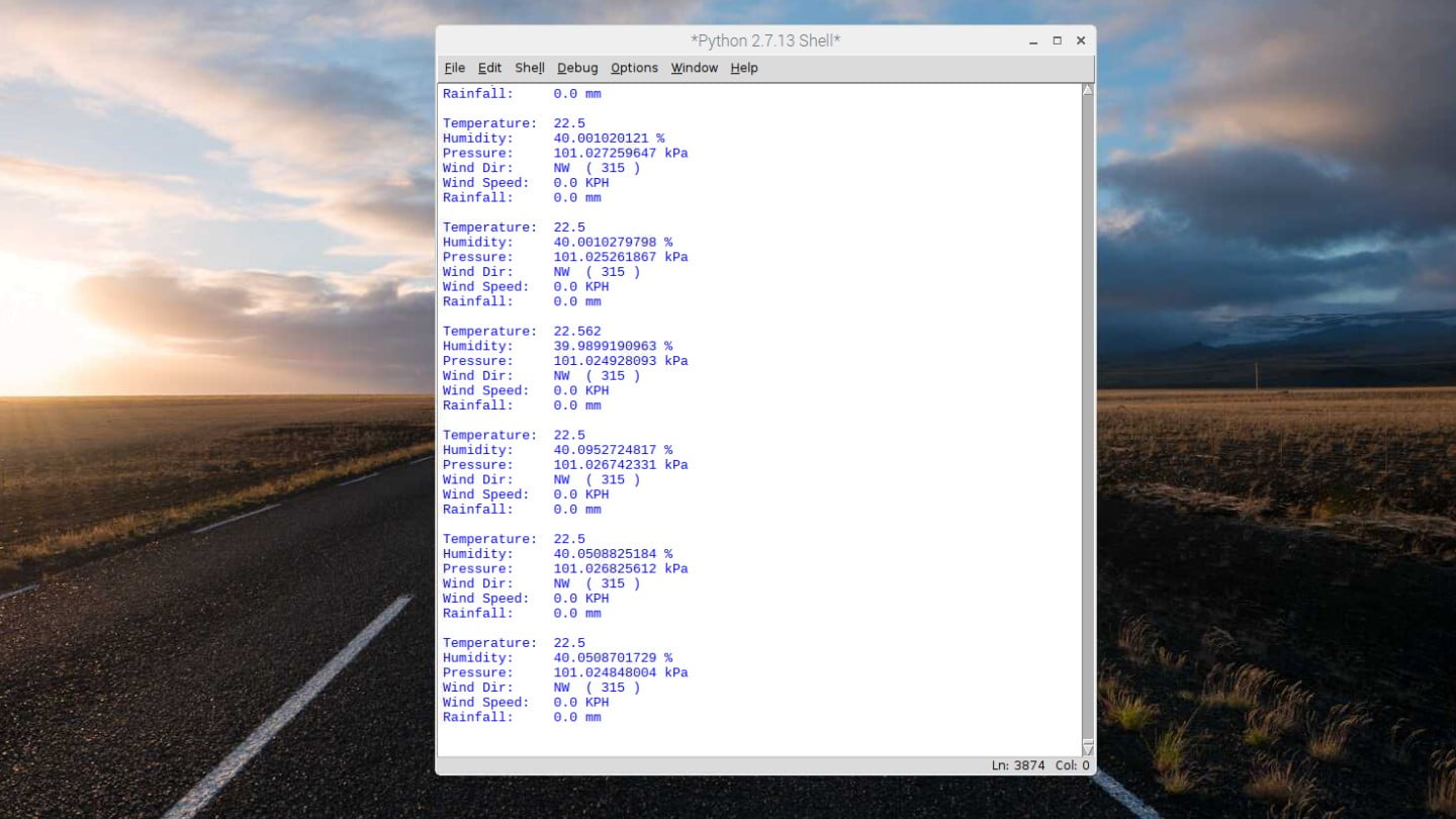
94.2%
Step 19 – All Done!
And that is it for our code! Hitting “F5” will run the program and should display all of the values every 15 seconds. Each sensor should respond, so feel free to try them all out. As always, if you have a question regarding the tutorial, please feel free to ask below!
In the next part of this tutorial we will be creating a Thingspeak account, modifying this program to send to Thingspeak, and looking at how this data can be used once it is logged there. Ready? Head on over to Part 3 of the Tutorial!
100%
129 thoughts on “Raspberry Pi Weather Station – Part 2”
AJ
Hi
When I set mine up everything was good, except the Wind Directions were backwards. you might want to check yours.
Chris @ BCR
Hi AJ,
I just fired ours up again with the code copied from the tutorial directly and it seems to be correct in our instance – when the nose of the wind vane is pointed to the “N” on the housing what do you get for an ADC reading?
Cheers,
scoobytoo
Ya your Right, I was just moving it around in my basement. added Dew point, Wind chill and a Feels like(humidex) values. I am workign on adding wind gust, average wind speed or rain in last hour. have you done any work on these values. I will be posting my code to git soon if anyone wants it.
Chris @ BCR
I have on my last Arduino based system – you may find that ThingSpeak does a fairly good job internally calculating this . For all of my systems i tend to just send all the raw data out to ThingSpeak, and do the remainder of the calculations and analysis on that end. Lots more on that coming in the next part 😉
mike87
not an expert but mine reads north when it points to the north so that’s right? Or is it the other way round?
Chris @ BCR
Hi Mike,
That’s right – the sensor will point into the wind (or towards the relative direction it is coming from) so that would be a correct reading.
Cheers,
jack
Hi Chris. Im having a issue with step 10. I give the command ls and don’t see the serial number of the sensor.
Thanks
Gus
I’m having the same problem, what do you mean by enable w1?
Chris @ BCR
You need to enable 1-wire – what happened when you completed step 8?
jack
sorry found the problem! enable w1
Chris @ BCR
No worries – glad you got it sorted!
Arjen
who can build for me this set ….im a dummy but searching for a WIFI weather station where i can wacth the weather on my beehives …..
any one a idea
Louis De Lange
Chris, I have a question re. the wind speed calibration used in your code above.
According to the sparkfun wind sensor data sheet the magnetic switch closes once per second for 2.4km/h wind.
In Step 19 line 20 you comment that there are 4 ticks per rotation – I am not sure where this comes from.
Then in line 114 to calculate average speed you use the number of ticks / the interval (15 secs) x 1.2 The calculation makes sense if you use 2.4km/h per tick per second, but I dont know where the 1.2 comes from.
Reason for the questions is that I am adding code so my station can report max wind gust during the interval and I need to make sure I understand the wind anemometer function correctly.
Chris @ BCR
Hi Louis,
I probably should have documented that one better – the sensor is actually capable of twice the resolution they state. Their information is based on measuring when the sensor is HIGH per revolution (so twice per rotation)
But, the interesting thing about this sensor is: if you measure the contact points, the sensor stays HIGH for ~90 degrees of rotation, and then stays LOW for ~90 degrees of rotation. Since the four transition points are spaced equally, we just measure the transition from HIGH to LOW and LOW to HIGH we can double the resolution of the sensor and get 4 ticks per revolution and 1.2km/h per tick, per second.
(Number of ticks * 1.2km/h) / 15 seconds = average wind speed
Hopefully that helps!
Louis De Lange
Chris,
Thanks, excellent explanation.
Of course, when the data sheet does not provide accurate info it leaves me much less confident of the 2.4km/h per rotation.
I prefer to calibrate the sensors with real known measurements, but wind speed is the one thing I dont have an easy and cheap way to check.
Chris @ BCR
Yeah that is a bit of a tricky one – it is also very subjective to your location so you cant really compare with stations near by.
One suggestion by another customer was to attach it to the outside of your car and drive at a low speed when the air is still. You could get data points at several speeds – but even car speedometers are ~ +/-10% so I’m not sure its worth the effort.
John Blood
weather project . in session 2 step 5 Iget error ensurepip is not defined .
pi@pi3two:~/Adafruit_Python_GPIO $ sudo python setup.py install
Traceback (most recent call last):
File “setup.py”, line 1, in
ensurepip
NameError: name ‘ensurepip’ is not defined
Chris @ BCR
Hi John,
Were there any errors when
sudo apt-get install build-essential python-pip python-dev python-smbus gitwas run?Chris @ BCR
Looks like Adafruit has depreciated the GPIO library – we will be rolling out new instructions for this soon
Gareth
Hi,
I get an error when executing, “sudo python setup.py install”
The error is; File “setup.py”, line 1, in
ensurepip
NameError: name ‘ensurepip’ is not defined
Any suggestions?
Thanks!
Chris @ BCR
Adafruit has depreciated most of their previous Python libraries and has now rolled out new Circuit Python libraries – there will be some changes to this tutorial (and several others) soon!
Gareth
Hi Chris,
Thanks for your reply.
As a matter of interest, do you have an approximate timeline when the new tutorials will be online?
Thanks again!
Gareth
Chris @ BCR
We are just modifying the instructions right now – for those that don’t want to wait:
– remove the old Adafruit GPIO directory
– run
sudo pip3 install --upgrade setuptools– run
pip3 install RPI.GPIO– run
pip3 install adafruit-blinkaand that should do it for that step. Every Adafruit library going forwards is going to have to be installed using the pip3 install method by the looks of things.. so:
sudo pip3 install adafruit-circuitpython-bme280
sudo pip3 install adafruit-circuitpython-ads1x15
Adafruit has seemingly removed their example files as well – so the commands for testing each device are no longer vaild.
Gareth
Thanks Chris.
If we apply these changes listed here, will anything else change in later parts?
Thanks again!
William @ BC Robotics
big changes… we gotta go to Python 3 (had to happen eventually) so probably best to hold for a day while we get this rewritten 🙂
Gareth
No problem at all.
Once again, thanks so much for being on the ball with this. It’s great to see such an awesome community.
You guys rock!
William @ BC Robotics
Thanks Gareth – it is now updated so give it a try. We are just firing through part 3 right now
jude
hi
Im getting this problem are entering
pip3 install adafruit-blinka
ollecting adafruit-blinka
Using cached https://www.piwheels.org/simple/adafruit-blinka/Adafruit_Blinka-5.13.1-py3-none-any.whl
Collecting sysv-ipc (from adafruit-blinka)
Using cached https://files.pythonhosted.org/packages/0c/d7/5d2f861155e9749f981e6c58f2a482d3ab458bf8c35ae24d4b4d5899ebf9/sysv_ipc-1.1.0.tar.gz
Complete output from command python setup.py egg_info:
Traceback (most recent call last):
File “”, line 1, in
File “/tmp/pip-build-eima54aa/sysv-ipc/setup.py”, line 11, in
import prober
File “/tmp/pip-build-eima54aa/sysv-ipc/prober.py”, line 137
d[“SYSV_IPC_VERSION”] = f'”{version}”‘
^
SyntaxError: invalid syntax
—————————————-
Command “python setup.py egg_info” failed with error code 1 in /tmp/pip-build-eima54aa/sysv-ipc/
please help
Chris @ BCR
Hello,
What version of Raspbian are you running?
John Blood
Thanks for the quick attention . I will await the changes
William @ BC Robotics
Should be good to go now John!
Gareth
Hi,
Thanks for the changes, it’s really appreciated!
One quick question. All the sensors work apart from the wind direction. When I hit F5, I get Wind Dir: Not connected (999)
However, it is plugged in.
When I disconnect it, I get the following:
Wind Dir: ESE (112.5)
Any thoughts?
Thanks so much once again!
Gareth
Just a quick update on this. It seems that when I hold the wind direction in a certain position, I get the ESE (112.5) message, but as soon as I change it, I get the ‘Not connected” message.
Thoughts?
Gareth
Also, when I spin the wind speed indicator, I get no reading.
Chris @ BCR
Hi Gareth,
Sounds like something isn’t plugged in right? Send us a few photos to support@bc-robotics.com and we can have a look.
Cheers!
Gareth
Hi Chris,
Sent. Thanks!
Gareth
John Blood
Thanks William
All good now !
John
John Here
I get not connected and 999 for wind direction .
Chris @ BCR
Hey John,
Double check your code – specifically line 70:
val = chan.value * 16John
I did a copy paste of your code and got the same result . I also printed chan.val and got 1644 no matter what direction vane was turned .I guess I am duplicating mssg here but suppose should have used reply !
John
I did a copy paste of your code and got the same result . I also printed chan.val and got 1644 no matter what direction vane was turned .
Chris @ BCR
Hi John,
Can you email over a few photos of your setup to support@bc-robotics.com ?
Gareth
Hi,
This is the error I get.
Was anyone able to sort out a fix?
Thanks!
Chris @ BCR
Hey Gareth,
This error would indicate that something isn’t plugged into the right socket. Double check your Anemometer is plugged into your Wind Direction sensor, and the long cable from your Wind Direction Sensor is plugged into the middle connector on the Weather Board.
Let us know if that doesn’t solve it!
Gareth
Hi,
Thanks for the reply. Much appreciated!
Yes, all the cables are correct.
Could it be anything else?
Thanks again!
Chris @ BCR
Hmm – that is a bit odd. Best bet is to send over an email to support@bc-robotics.com referencing this post. They can drill down and help troubleshoot much more in depth!
Gareth
Hi,
I sent an email earlier this week. We’re you able to investigate?
Cheers
Gareth
Chris @ BCR
Hi Gareth,
Just checked with Support – they wrote back earlier in the week and are waiting on photos – Cheers!
Gareth
Hi,
I didn’t actually get an email from them but I had sent through some pics previously. Did they receive them?
Chris @ BCR
Hi Gareth,
Looks like they replied on April 9 @ ~ 2:58PM. I just had someone resend – double check the junk folder if you don’t see it!
Gareth
Hi Chris,
The reply I got was for the initial, change of tutorial problem.
Is there any word on this latest issue?
Thanks again!
Cheers
Gareth
Gareth
Hi John,
Were you able to fix this error? I get the same one.
Dave Enstrom
Question on wind speed … from SparkFun ” A wind speed of 1.492 MPH (2.4 km/h) causes the switch to close once per second”.
So your conversion of “windSpeed = (windTick * 1.2) / interval” doesn’t seem to make sense
Should it be “windSpeed = (windTick * 2.4) / interval”?
PS: My microSD card failed, so currently updating my Pi and WeeWX driver to Python 3. I’ll let you know when available on GitHub.
Chris @ BCR
Hey Dave – the sensor is actually capable of twice the resolution they state. Their information is based on measuring when the sensor is HIGH per revolution (so twice per rotation)
But, the interesting thing about this sensor is: if you measure the contact points, the sensor stays HIGH for ~90 degrees of rotation, and then stays LOW for ~90 degrees of rotation. Since the four transition points are spaced equally, we just measure the transition from HIGH to LOW and LOW to HIGH we can double the resolution of the sensor and get 4 ticks per revolution and 1.2km/h per tick, per second.
(Number of ticks * 1.2km/h) / 15 seconds = average wind speed
Hopefully that helps!
Dave Enstrom
An update: Forgot that WeeWX only runs on Python V2 … so the driver will not be updated.
George
Hi Dave,
I’m trying to do the same think (RPi + weewx).
Do you have any links to drivers or a general description of your software setup?
Thank in advance!
Ron
I’m a newbie and had the same problem as Jack in reply 8, no ID returned for w1. what is the specific command for enabling w1.
Thanks
William @ BC Robotics
Hi Ron, best bet is to hit the Raspberry Menu in the top left corner, go down to Preferences and select Raspberry Pi Configuration. Under the “Interfaces Tab” make sure 1-Wire is set to enable.
(and I2C while you are there, it will be needed as well!)
Ron
thank you…
Juan
Hi, I need to set up a remote weather station and I would like to know if instead of reading wind directions in an approximate manner, can I obtain the wind direction in degrees (0 – 359º)?
William @ BC Robotics
Hi Juan
Yes, but you would need to get a different wind direction meter that can provide that level of resolution. Most hobby / home grade out there are only capable of 16 directions.
Juan
Hi William, thanks for your reply. Could you give me a link to a wind direction meter that can provide 360 degree resolution and that can be connected to this RPi weather station?
Juan
I have another question: where can I obtain solar radiation and UV sensors that can be connected to this weather station?
William @ BC Robotics
The Weather Board breaks out all of the data buses available on the Pi and has three extra analog inputs, so there is plenty of room for expansion.
What sensor to use for each will depend on how accurate you need it to be.
Juan
What I really need is a solar radiation sensor that can help determine plant growth.
Dave
Hi Everyone, just got my weather station up and running using weeWX, but it’s having an error problem with wind direction ie: weeWX [440]: BCRobo: MainThread: wind direction error: 26368
26384
25808
all errors seem to be around the 25k t0 26k range and just wondering if anybody knows what causing this, I’m thinking defective sensor
Chris @ BCR
Hey Dave,
Most likely a software issue – it is still providing you a reading so the ADC and the resistive sensor are doing their thing. Not being familiar with the weeWX, i would guess it is probably how the data is being interpreted. Best bet to rule out the sensor / ADC is to run our tutorial code on a fresh installation. There have been a lot of changes to some of the libraries we use in the past ~ 3 months.
Dave
Thanks Chris
I have run the BCR test app and the problem does not show up, so then it must have to do with how weeWx interprets the data from the BCR driver
Chris @ BCR
We use the Adafruit ADS library – this has changed significantly in the past few months so my first hunch would be to check there. The way the gain was handled changed which caused some issues within our example code.
Dave
I will try updating and see if that gets rid of the errors
Thanks for the help
dia-sea
I’m also print “Not Connected” at windDir with new code.
What is this value based on?
val = chan.value * 16
if 20000 <= val <= 20500:
if 10000 <= val <= 10500:
if 11500 <= val <= 12000:
if 2000 <= val <= 2250:
if 2300 <= val <= 2500:
if 1500 <= val <= 1950:
if 4500 <= val <= 4900:
if 3000 <= val <= 3500:
if 7000 <= val <= 7500:
if 6000 <= val <= 6500:
if 16000 <= val <= 16500:
if 15000 <= val <= 15500:
if 24000 <= val <= 24500:
if 21000 <= val <= 21500:
if 22500 <= val <= 23000:
if 17500 <= val <= 18500:
I found the data on the condition of 5V in the WeatherMeters datasheet.
WeatherMeters dataseet
https://www.sparkfun.com/datasheets/Sensors/Weather/Weather%20Sensor%20Assembly..pdf?_ga=2.198458284.2051866801.1558002594-1193397126.1558002594
However, the voltage of real circuit was 3V.
I could't found the condition of 3V.
Sorry, I'm a Japanese person with poor English.
Chris @ BCR
No worries!
Since this is an analog sensor, the voltage doesn’t really matter as long as your input voltage and your analog reference are the same. In this case both are 3V so it will work. The values are pulled from the ADS1015 Analog to Digital Converter by way of the Adafruit ADS1x15 Python Library – This library has been updated and the Gain has been changed – if you have an old version of the library installed it could be causing issues.
dia-sea
Thank you for reply.
I understand it works.
The following is a different topic.
I think that old sample source code use ADS1115.
So I measured voltage between “wind R11 connecter” 1pin to 4pin with multimeter.
It was similar to the value output by the following sample code with ADS1115.
import adafruit_ads1x15.ads1115 as ADS
from adafruit_ads1x15.analog_in import AnalogIn
i2c = busio.I2C(board.SCL, board.SDA)
ads = ADS.ADS1115(i2c)
ads.gain = 1
chan = AnalogIn(ads, ADS.P0)
print(chan.voltage)
————————————————————
direction: N / multimeter: 2.51V / sample code output 2.548V
direction: E / multimeter: 0.28V / sample code output 0.302V
direction: S / multimeter: 0.91V / sample code output 0.934V
direction: W / multimeter: 3.02V / sample code output 3.066V
————————————————————
I think this board use ADS1115 for A/D converter isn’t it?
And I tried calucration following this code.
This system use dataseet value.
https://os.mbed.com/users/okini3939/code/WeatherMeters/file/6a62f29b1bb5/WeatherMeters.cpp/
I can get wind direction resistance (Ohms).
ohm = chan.voltage / ((3.3 – chan.voltage) / 10000.0)
Wind Dir: N( 0.0) 2.546V 33887.517Ohm
Wind Dir: N( 0.0) 2.548V 33797.618Ohm
Wind Dir: N( 0.0) 2.548V 33860.918Ohm
Wind Dir: NNE(22.5) 1.316V 6633.401Ohm
Wind Dir: NE(45.0) 1.496V 8293.146Ohm
Wind Dir: NE(45.0) 1.496V 8304.233Ohm
Wind Dir: NE(45.0) 1.498V 8293.146Ohm
Wind Dir: ENE(67.5) 0.272V 898.313Ohm
Wind Dir: E(90.0) 0.302V 1007.372Ohm
Wind Dir: E(90.0) 0.304V 1008.045Ohm
Wind Dir: E(90.0) 0.302V 1014.043Ohm
Wind Dir: ESE(112.5) 0.214V 693.477Ohm
Wind Dir: SE(135.0) 0.600V 2222.305Ohm
Wind Dir: SSE(157.5) 0.410V 1418.735Ohm
Wind Dir: S(180.0) 0.934V 3947.759Ohm
Wind Dir: SSW(202.5) 0.794V 3168.523Ohm
Wind Dir: SW(225.0) 2.042V 16191.770Ohm
Wind Dir: SW(225.0) 2.042V 16233.414Ohm
Wind Dir: SW(225.0) 2.042V 16217.514Ohm
Wind Dir: WSW(247.5) 1.942V 14301.502Ohm
Wind Dir: W(270.0) 3.064V 129970.716Ohm
Wind Dir: W(270.0) 3.066V 131082.056Ohm
Wind Dir: Not Connected(999.0) 3.066V 132212.564Ohm
Wind Dir: WNW(292.5) 2.684V 43611.026Ohm
Wind Dir: NW(315.0) 2.878V 68215.331Ohm
Wind Dir: NW(315.0) 2.878V 68262.736Ohm
Wind Dir: NW(315.0) 2.878V 68540.244Ohm
Wind Dir: NW(315.0) 2.880V 68587.875Ohm
Wind Dir: NNW(337.5) 2.280V 22311.396Ohm
Wind Dir: NNW(337.5) 2.278V 22335.539Ohm
Wind Dir: N( 0.0) 2.548V 33887.517Ohm
Chris @ BCR
Ahh ok , i see what you are asking – our numbers are based on raw ADC output. However, you could use voltage or calculated resistance as well – that is much more a matter of preference at that point.
Dave
Hi dia-sea, so you have been getting the not connected error, what i have found if your using the Argent weather vane is that the reed switches can degrade over time as in my case, replaced all switches which has fixed some errors. Where the problem seems to be is when the magnet is between two switches, if one or both switches do not close you’ll get an error particularly in the NNE, ENE, SSW and so on and you’ll get the 26363, 26252 and so on errors.I read a doc. on SwitchDoc Labs about the 16 possible directions which they say are rare. Software updates did not help as chris suggested. I have order a new wind vane to see if this helps as mine is over 10yrs old. hope this helps
Chris @ BCR
Interesting point Dave – the other side of it may be that the magnet is degrading over time – if the effective field shrinks it could leave gaps between directions as well.
dia-sea
Hi, Dave
I use unused wind vane, but that bought for spare 6 years ago.
I get “Not Connected”, I think that reason is range.
I referred to this source code.
https://os.mbed.com/users/okini3939/code/WeatherMeters/file/6a62f29b1bb5/WeatherMeters.cpp/
In this source code, the resistance value “x0.9” to “x1.1″ is used as a range of direction.
By adjusting the value, I think to get current direction without error.
I’m trying this source code.
———————————————–
import time
import board
import busio
import adafruit_ads1x15.ads1115 as ADS
from adafruit_ads1x15.analog_in import AnalogIn
i2c = busio.I2C(board.SCL, board.SDA)
ads = ADS.ADS1115(i2c)
ads.gain = 1
# dataseet values
tbl_windvane=[[0.0,33000,”N”],[22.5,6570,”NNE”],[45.0,8200,”NE”],[67.5,891,”ENE”],
[90.0,1000,”E”],[112.5,688,”ESE”],[135.0,2200,”SE”],[157.5,1410,”SSE”],
[180.0,3900,”S”],[202.5,3140,”SSW”],[225.0,16000,”SW”],[247.5,14120,”WSW”],
[270.0,120000,”W”],[292.5,42120,”WNW”],[315.0,64900,”NW”],[337.5,21880,”NNW”]]
interval = 1
while True:
time.sleep(interval)
chan = AnalogIn(ads, ADS.P0)
ohm = chan.voltage / ((3.3 – chan.voltage) / 10000.0)
windDir = “Not Connected”
windDeg = 999
for windvane in tbl_windvane:
if windvane[1]*0.9 <= ohm <= windvane[1]*1.1: # Need to ajust this value
windDir = windvane[2]
windDeg = windvane[0]
print ("Wind Dir: {}({:4.1f}) {:1.3f}V {:6.3f}Ohm".format(windDir,windDeg,chan.voltage,ohm))
Dave
Hi Chris, replaced wind direction sensor with a new one and errors are gone and I have all 16 points so no software issue here just mechanical and once again thanks for your help and the tutorials, now I’ve got to figure how to write the programming for UV and Lux senors just beginning to get my head around python
Chris @ BCR
No worries!
Dave
That was what I’ve been thinking, with the board out of the housing and with another similar magnet I can get all 16 point which made me think of alignment or bad magnet
Ron
Having trouble with the rain sensor. Rain tick does not increase with bucket movement. On checking found that on the RJ11 connector one of the middle two wires measures 0.0vdc (Pi GRD), but the other is floating. I expected it to read (Pi) 3.33vdc. Thanks for any help
Ron
should have noted, GPIO 23 reads 3.33vdc on the Pi header.
Chris @ BCR
Hi Ron,
That is correct – the GPIO pin is being pulled high
GPIO.setup(23, GPIO.IN, pull_up_down=GPIO.PUD_UP)When the rain gauge tips, the reed switch will close to ground and the Pi should register that. It only should register for a very short period of time as it crosses center to tip the other direction
#Event to detect rainfall tickGPIO.add_event_detect(23, GPIO.FALLING)
def raintrig(self):
global rainTick
rainTick += 1
GPIO.add_event_callback(23, raintrig)
Ron
That is how I believed it should work also. Is’nt GPIO (23) tied directly to one of the RJ11 pins? If so, I should be able to measure 3.33vdc at the RJ11 connector, which I do not.
Ron
Thanks for you help, I found the problem. I failed to solder GPIO pin 23 on the header to the weather board. Only one I missed. I’m 80, so guess I better check on getting new glasses, ha.
Dave
Is there a product to coat the boards to protect them from the outdoor environment??
William @ BC Robotics
Conformal coating (we don’t carry it, pressurized cans of chemicals are not fun to ship!)
Dave
Thanks
Simone
You dais above: “The Pi has an easy way of monitoring this sort of thing. Even though we have paused the entire program for a period of 15 seconds, we can create a background process that will still watch for changes in this pin and keep count while the main code is paused.”
How could I change the code implementing the wind speed measurement in background while in those 15 seconds do other things?
Simone
One more question. Do you consider the code below a valid alternative to measure the wind speed based on the time it actually takes to do a full revolution (as opposed to wait for a fixed interval)?
def calculate_elapse(channel): # callback function
global pulse, start_timer, elapse, speed
pulse += 1 # increase pulse by 1 whenever interrupt occurred
if pulse == 4:
elapse = time.time() – start_timer # elapse for every 1 complete rotation made!
start_timer = time.time() # let current time equals to start_timer
speed = pulse * 2.4 / elapse
pulse = 0
Chris @ BCR
Your logic is correct, you could measure the time it takes to complete a revolution and figure it out from there rather than the number of revolutions in a span of time.
There are 4 ticks per revolution, 2 rising and two falling. Using both gives you slightly better resolution. So depending on how you approach it you will need to use the right calculation. If you use both, it is 1.2km/h per tick in a one second interval.
DaveE
A suggestion re: DS18B20 temperature sensor software library. I think the command should be:
$ sudo pip3 install w1thermsensor -U
Your direction will result in installing an old version I think. Yes?
Fabio
Goodmorning,
I assembled the weather station but i’ve only one problem: Wind direction seems does’nt works.
I’ve ever 999 degrees!
All other sensors working fine.
What’s the problem?
How I read the real value in output of the dac?
Thanks
Fabio
Michael Grainger
Good day:
This is a great project my only question has to do with the humidity reading. indicating 16.9 % in a room where the humidity is 58 %.
Any ideas as to the issue, bad sensor?
Regards,
Mike
Chris @ BCR
Hey Mike,
There are a couple things that could be causing it – what version of the board are you running? WeatherHat (RAS-139) with the Adafruit BME Breakout installed, or a WeatherHAT Pro with the BME already installed?
Gary
Hi guy
We download the latest operating system and had more luck get the comands to load on. But we got to the very last command step 10 and we are getting error unable to locate package python3-w1therms. Thanks again
Gary
Fixed now was using a phone to read comands and was missing the last part of it on the phones screen
jude
Thanks for the quick reply Chris.
we are running the image that is mentioned in the tutorial raspbain 27.6.2018.
jude
hi
Im getting this problem are entering
pip3 install adafruit-blinka
ollecting adafruit-blinka
Using cached https://www.piwheels.org/simple/adafruit-blinka/Adafruit_Blinka-5.13.1-py3-none-any.whl
Collecting sysv-ipc (from adafruit-blinka)
Using cached https://files.pythonhosted.org/packages/0c/d7/5d2f861155e9749f981e6c58f2a482d3ab458bf8c35ae24d4b4d5899ebf9/sysv_ipc-1.1.0.tar.gz
Complete output from command python setup.py egg_info:
Traceback (most recent call last):
File “”, line 1, in
File “/tmp/pip-build-eima54aa/sysv-ipc/setup.py”, line 11, in
import prober
File “/tmp/pip-build-eima54aa/sysv-ipc/prober.py”, line 137
d[“SYSV_IPC_VERSION”] = f’”{version}”‘
^
SyntaxError: invalid syntax
—————————————-
Command “python setup.py egg_info” failed with error code 1 in /tmp/pip-build-eima54aa/sysv-ipc/
please help
Chris @ BCR
Hi Jude,
That is a little odd – try running update again:
[code]sudo apt-get update[/code]
and then run:
[code]pip3 install adafruit-blinka[/code]
see if that solves it…
Gary
Traceback (most recent call last):
File “/usr/local/lib/python3.7/dist-packages/adafruit_bus_device/i2c_device.py”, line 154, in __probe_for_device
self.i2c.writeto(self.device_address, b””)
File “/home/pi/.local/lib/python3.7/site-packages/busio.py”, line 158, in writeto
return self._i2c.writeto(address, buffer, stop=stop)
File “/home/pi/.local/lib/python3.7/site-packages/adafruit_blinka/microcontroller/generic_linux/i2c.py”, line 49, in writeto
self._i2c_bus.write_bytes(address, buffer[start:end])
File “/home/pi/.local/lib/python3.7/site-packages/Adafruit_PureIO/smbus.py”, line 308, in write_bytes
self._device.write(buf)
OSError: [Errno 121] Remote I/O error
During handling of the above exception, another exception occurred:
Traceback (most recent call last):
File “/usr/local/lib/python3.7/dist-packages/adafruit_bus_device/i2c_device.py”, line 160, in __probe_for_device
self.i2c.readfrom_into(self.device_address, result)
File “/home/pi/.local/lib/python3.7/site-packages/busio.py”, line 148, in readfrom_into
return self._i2c.readfrom_into(address, buffer, stop=stop)
File “/home/pi/.local/lib/python3.7/site-packages/adafruit_blinka/microcontroller/generic_linux/i2c.py”, line 56, in readfrom_into
readin = self._i2c_bus.read_bytes(address, end – start)
File “/home/pi/.local/lib/python3.7/site-packages/Adafruit_PureIO/smbus.py”, line 179, in read_bytes
return self._device.read(number)
OSError: [Errno 121] Remote I/O error
During handling of the above exception, another exception occurred:
Traceback (most recent call last):
File “/home/pi/BME280.py”, line 9, in
bme = adafruit_bme280.Adafruit_BME280_I2C(i2c)
File “/usr/local/lib/python3.7/dist-packages/adafruit_bme280.py”, line 534, in __init__
self._i2c = i2c_device.I2CDevice(i2c, address)
File “/usr/local/lib/python3.7/dist-packages/adafruit_bus_device/i2c_device.py”, line 50, in __init__
self.__probe_for_device()
File “/usr/local/lib/python3.7/dist-packages/adafruit_bus_device/i2c_device.py”, line 163, in __probe_for_device
raise ValueError(“No I2C device at address: 0x%x” % self.device_address)
ValueError: No I2C device at address: 0x77
Please help getting this for all sensors except the temperature.
thanks
William @ BC Robotics
Do you have I2C enabled in raspi-config?
George
Hello again,
trying to install on a freshly updated OS and I get this error:
import adafruit_bme280
ModuleNotFoundError: No module named ‘adafruit_bme280’
I think it has something to do with an recent update since I didn’t get this error one week ago.
Chris @ BCR
Hi George,
You are correct – things have changed – we are just in the process of updating the entire tutorial. The BME library has changed the way the chipset is addressed again:
line 6 changes to: [code]from adafruit_bme280 import basic as adafruit_bme280[/code]
line 7 changes to: [code]i2c = board.I2C() # uses board.SCL and board.SDA[/code]
line 9 changes to: [code]bme = adafruit_bme280.Adafruit_BME280_I2C(i2c)[/code]
that *should* solve it – but let us know if you run into anything else!
George
Thank you Chris for the quick reply!
I will try the changes and also wait for the updated tutorial.
George
Hello again Chris,
no luck with the changes, there is still the same error.
I think it has something to do with the libraries’ order of installation.
George
Hi Chris,
do you have a rough ETA for the updated tutorial?
Asking so I can schedule my visit to the site.
Thank you in advance.
Chris @ BCR
Hi George,
No worries – We are looking to have it up in the next 10 days
George
Hey Chris,
that is great!
Thank you very much for your efforts!
George
Hey Chris,
any news about the tutorial?
Thank you once again!
William @ BC Robotics
Updated – the example code now reflects the new Adafruit BME280 Library.
Mark
FYI George, I also needed to make these changes and it worked for me when I left the line:
i2c = board.I2C() # uses board.SCL and board.SDA
as
i2c = busio.I2C(board.SCL, board.SDA)
Hope this helps and thanks to BC-Robotics for this excellent tutorial!
Mark
izzi
Hi,
I’ve written the code and loaded all the files in terminal with the exception of an error message of unknown command for the “1s” test line.
My python code is reading that it has no errors and I am getting the restart message in the python 3.7.3 shell. However, nothing happens after that and I haven’t been able to get any data readings. Not sure where to go to trouble shoot or what the problem may be.
Any help is really appreciated!!
Paolo Fiumarella
hello I need to read the converted bit value of the direction sensor, how do I do it?
Paolo Fiumarella
Hi, i’m building the weather station and i’m following its tutorial, but i have a problem, when i detach the sensor bme_280 the python script is not executed, how can i solve this problem?
Dave Aldous
Hi Chris
I’m getting a similar error as Jude with the pip3 install adafruit-blinka command. I get:
SyntaxError: Invalid syntax
Command “python setup.py egg_info” failed with error code 1 in /tmp/pip-build-e6qibl9a/sysv-ipc/
I’m also running Raspbian 2018-06-27
Thanks for your quick reply to my Part 1 question.
Joseph Sherrill
Something amiss. Am I fetching proper library? Python code is as in the tutorial:
import time
from w1thermsensor import W1ThermSensor
import board
import busio
from adafruit_bme280 import basic as adafruit_bme280
i2c=busio.I2C(board.SCL,board.SDA)
bme=adafruit_bme280.Adafruit_BME280_I2C(i2c)
ds18b20 = W1ThermSensor()
interval = 15 #How long we want to wait between loops(seconds)
while True:
time.sleep(interval)
#Pull Temperature from DS18B20
temperature = ds18b20.get_temperature()
#Pull temperature from BME280
case_temp=bme.temperature
#Pull pressure from BME280 Sensor and convert to kPa
pressure_pa=bme.pressure
pressure=pressure_pa/10
#Pull humidity from BME280
humidity=bme.humidity
#Print the results
print(‘Temperature:’,temperature)
print(‘Humidity:’,humidity,’%’)
print(‘Pressure:’,pressure,’kPa’)
print(”)
#Print the results
print(‘Temperature:’,temperature)
Yet I am getting following error reports:
%Run ReadBME.py
Traceback (most recent call last):
File “/usr/local/lib/python3.7/dist-packages/adafruit_bus_device/i2c_device.py”, line 154, in __probe_for_device
self.i2c.writeto(self.device_address, b””)
File “/home/pi/.local/lib/python3.7/site-packages/busio.py”, line 166, in writeto
return self._i2c.writeto(address, buffer, stop=stop)
File “/home/pi/.local/lib/python3.7/site-packages/adafruit_blinka/microcontroller/generic_linux/i2c.py”, line 49, in writeto
self._i2c_bus.write_bytes(address, buffer[start:end])
File “/home/pi/.local/lib/python3.7/site-packages/Adafruit_PureIO/smbus.py”, line 314, in write_bytes
self._device.write(buf)
OSError: [Errno 121] Remote I/O error
During handling of the above exception, another exception occurred:
Traceback (most recent call last):
File “/usr/local/lib/python3.7/dist-packages/adafruit_bus_device/i2c_device.py”, line 160, in __probe_for_device
self.i2c.readfrom_into(self.device_address, result)
File “/home/pi/.local/lib/python3.7/site-packages/busio.py”, line 156, in readfrom_into
return self._i2c.readfrom_into(address, buffer, stop=stop)
File “/home/pi/.local/lib/python3.7/site-packages/adafruit_blinka/microcontroller/generic_linux/i2c.py”, line 56, in readfrom_into
readin = self._i2c_bus.read_bytes(address, end – start)
File “/home/pi/.local/lib/python3.7/site-packages/Adafruit_PureIO/smbus.py”, line 181, in read_bytes
return self._device.read(number)
OSError: [Errno 121] Remote I/O error
During handling of the above exception, another exception occurred:
Traceback (most recent call last):
File “/home/pi/ReadBME.py”, line 9, in
bme=adafruit_bme280.Adafruit_BME280_I2C(i2c)
File “/usr/local/lib/python3.7/dist-packages/adafruit_bme280/basic.py”, line 366, in __init__
self._i2c = i2c_device.I2CDevice(i2c, address)
File “/usr/local/lib/python3.7/dist-packages/adafruit_bus_device/i2c_device.py”, line 50, in __init__
self.__probe_for_device()
File “/usr/local/lib/python3.7/dist-packages/adafruit_bus_device/i2c_device.py”, line 163, in __probe_for_device
raise ValueError(“No I2C device at address: 0x%x” % self.device_address)
ValueError: No I2C device at address: 0x77
>>>
BTW, i2cdetect shows nothing at 0x76 or 0x77. The board IS an Adafruit BME280.
William @ BC Robotics
Not a library issue – this would be related to a hardware / connection issue. Double check all connections, ensure I2C is enabled in Raspi Config, and work outwards from there
David Enstrom
You need to update step 10 to:
sudo pip3 install w1thermsensor
Steven
I’m having issues with step 10
I have followed the directions precisely but I keep getting
error unable to locate package python3-w1thermsensor
Any suggestions?
Chris @ BCR
Hi Steven,
Just tested it again with
sudo apt-get install python3-w1thermsensoror
sudo pip3 install w1thermsensorand they both worked? what version of the OS are you running?
Steven
Sorry the the delayed response. I just started over and I got it to work now. I’m using the latest version of Raspbian.
Now I’m just trying to figure out the codes. Stuck on step 14 as I can’t get it to print out any results but I’ll power through.
Philippos Koutsakas
Hi and many thanks for the excellent project…
I am having problems trying in this point…
$ sudo pip3 install –upgrade setuptools
error: externally-managed-environment
× This environment is externally managed
╰─> To install Python packages system-wide, try apt install
python3-xyz, where xyz is the package you are trying to
install.
If you wish to install a non-Debian-packaged Python package,
create a virtual environment using python3 -m venv path/to/venv.
Then use path/to/venv/bin/python and path/to/venv/bin/pip. Make
sure you have python3-full installed.
For more information visit http://rptl.io/venv
note: If you believe this is a mistake, please contact your Python installation or OS distribution provider. You can override this, at the risk of breaking your Python installation or OS, by passing –break-system-packages.
hint: See PEP 668 for the detailed specification.
Any suggestions?
Many thanks
Jumbo
Hi
Im having an issue from the start
I get “error: externally-managed-environment” when trying to run “sudo pip3 install –upgrade setuptools”
Chris @ BCR
This happens with the newest version of the Raspberry Pi OS, see our guide on Virtual Environments in Python for solutions: https://bc-robotics.com/tutorials/virtual-environments-in-python-on-raspberry-pi/
denstrom
I am running “Bookworm” and trying to setup the software as defined above. Got the virtual environment going, and everything seems fine, however I am getting the error “Failed to add edge detection” when setting up GPIO pins 17 and 23. I have tried running my test app using SUDO, and also tried the rpi-lgpio library (as discovered on various forums). Still no go … and ideas on what is going on?
DEnstrom
I have figured out the issue. Bookworm does not support Rpi.GPIO. Therefore I have switched to using GPIOZERO in my BCRobotics.py driver for WeeWX, and for the test app. See: https://github.com/David-Enst/WeeWX-BCRobotics
chris
hi all
help please , i have successfully got to the part of getting temperature sensor reading ,but when trying to get BME280 to work not having any
i have done a i2c detect and its on address 48 , is this right , i copied all code correct , when putting cod in terminal i get at the end , you should be running a virtual enviroment .
but dont get any errors
the BME280 is the same as one shown in website tutorial
any help would be great please
i am a beginner at this so go steady please
chris
William @ BC Robotics
This is an issue with the version of Raspbian you are running – new versions “require” the use of virtual python environments – we have a guide here: https://bc-robotics.com/tutorials/virtual-environments-in-python-on-raspberry-pi/