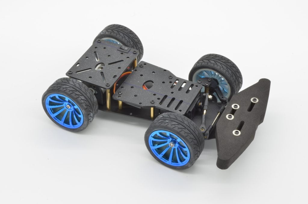
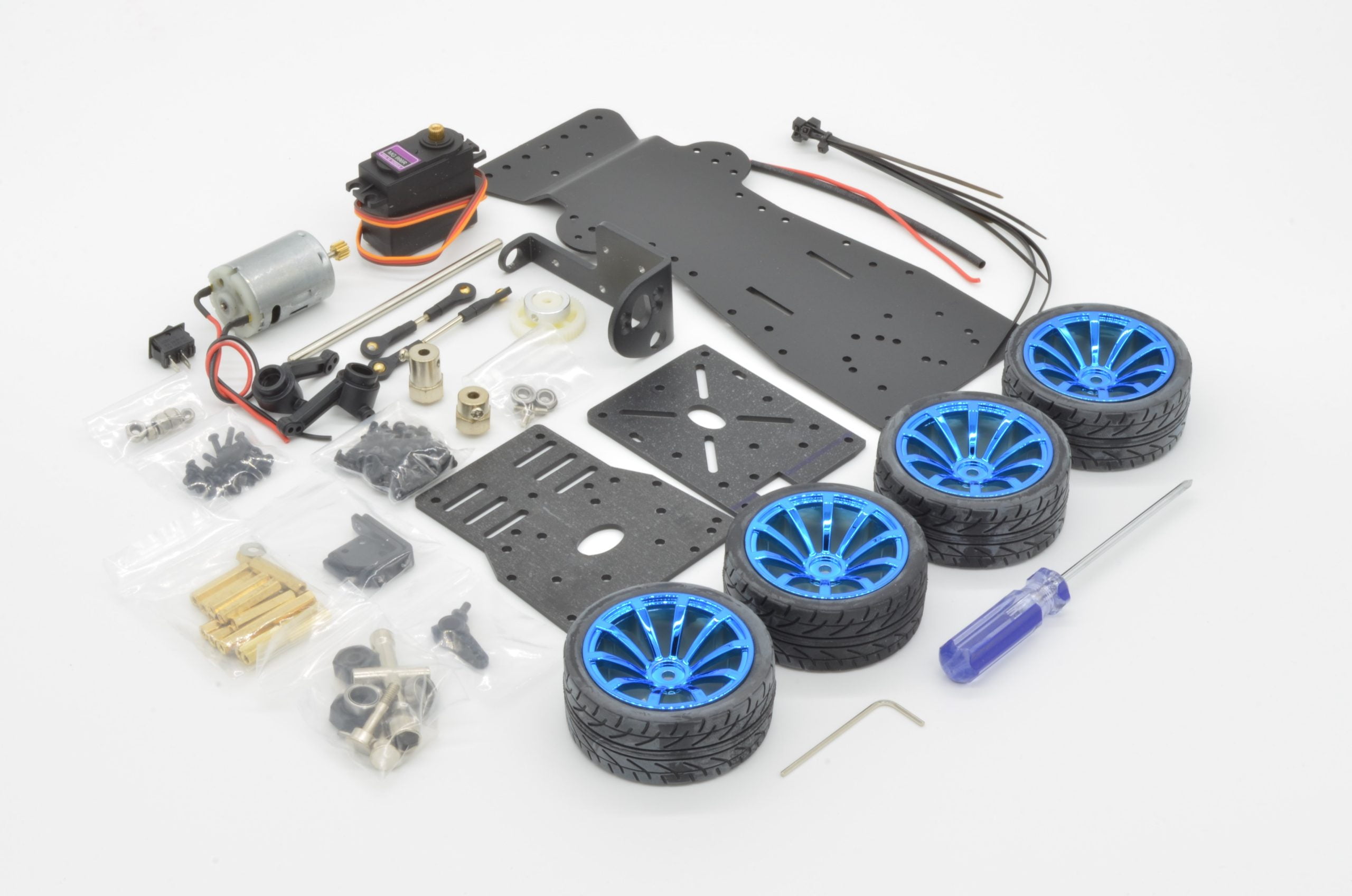
In this tutorial we are going to assemble our 2WD Metal Chassis. These are a bit more complex than some of our other robot chassis so a visual guide is a must. The chassis features a variety of different hardware so pay careful attention to which screws are required in each step.
About The Chassis:
This chassis is a little different than most we offer – rather than independently driven wheels, which allows for direction and speed control through individual control of wheel speeds, this chassis uses a single powerful drive motor and a steering rack similar to the drivetrain of a typical car.
Recommended Tools
While this kit does include a couple tools to help with assembly, we do recommend a few additional tools to make assembly a little easier. Screws this size are quite delicate and using the wrong sized screwdriver can cause them to strip out or wreck the finish.
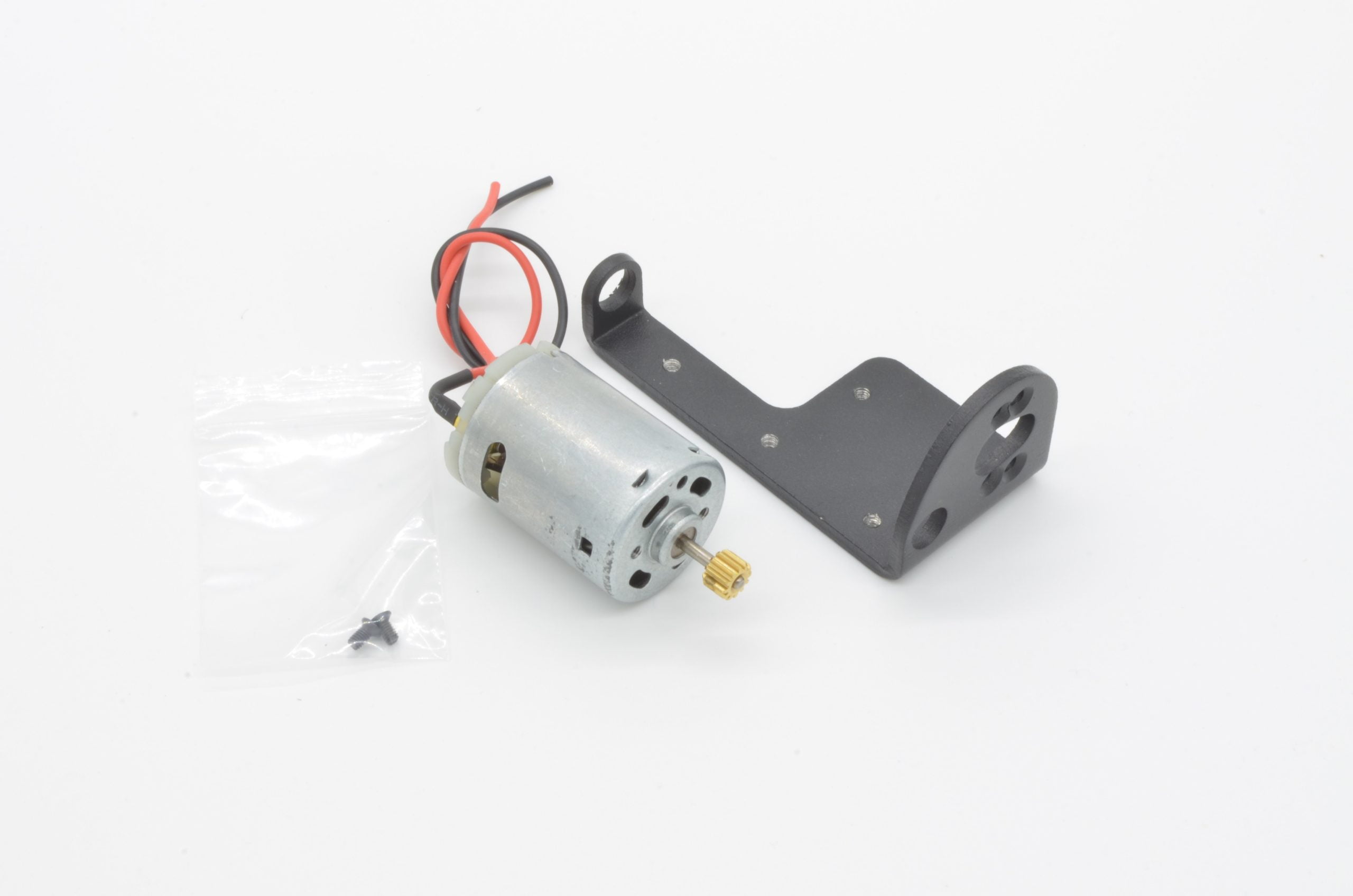
We are going to start by assembly the rear motor and driveshaft assembly. The motor mounts to a very nice bracket that houses the rear axle bearings and hubs. If this sounds a bit complex: not a worry! We will be going through this step by step.
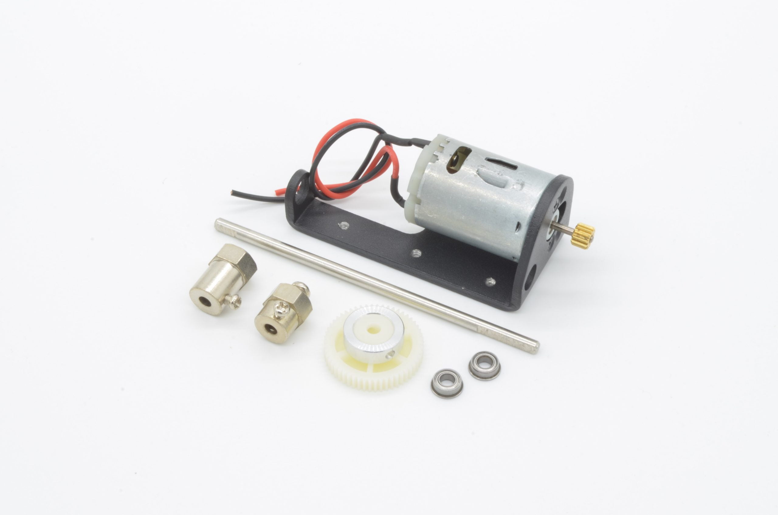
First start by finding the motor, the motor mount, and a small bag with two tiny screws. These screws differ from most of the kit as they have a countersunk head.
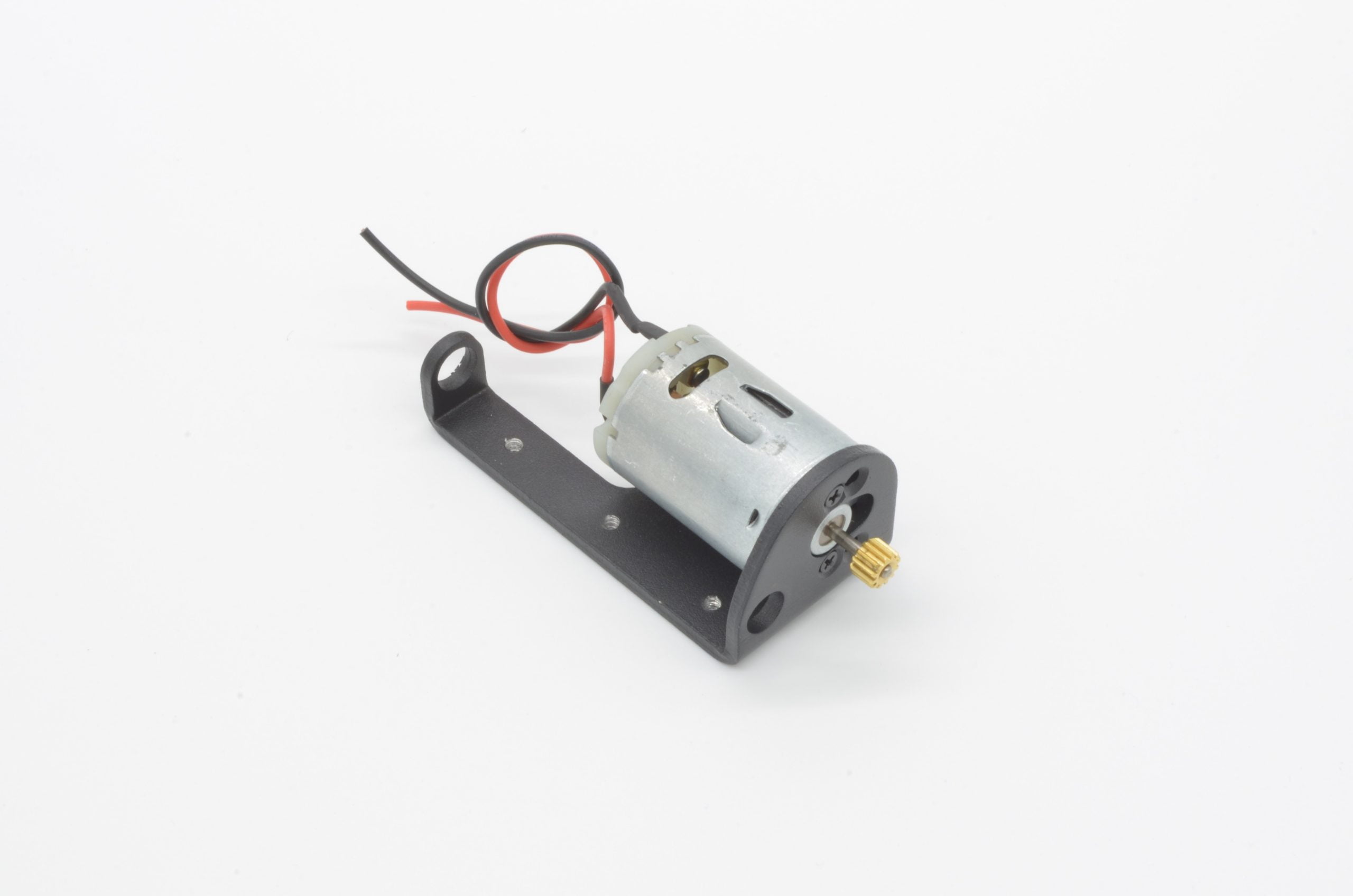
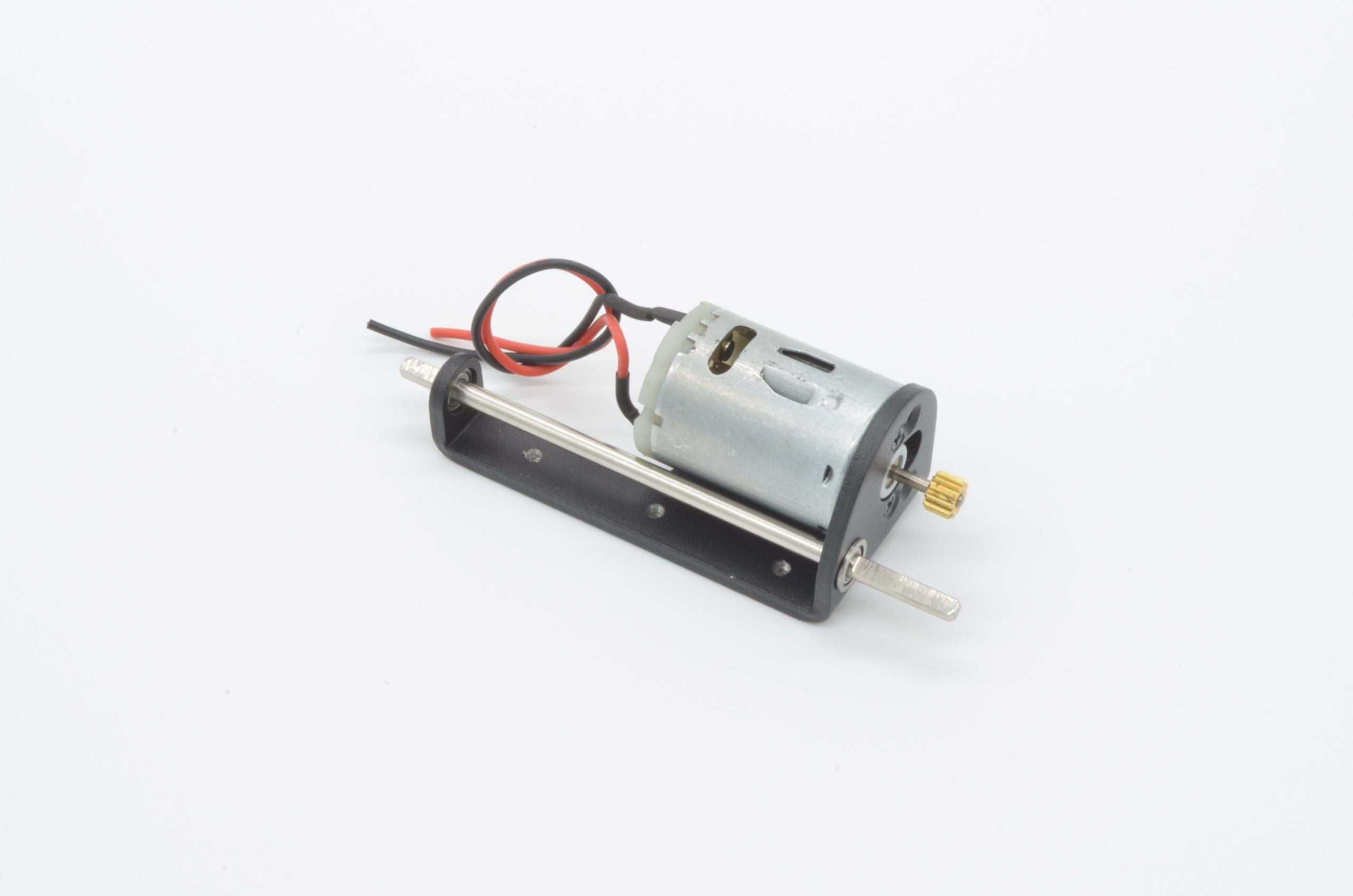
Fitting the motor can take a bit of fiddling around to get the screws to line up. Once completed, the assembly should look like this. We are now ready to fit the bearings, axle, gear, and rear wheel hubs.
7%
Step 2 - The Driveshaft Assembly
Next we are going to assemble the rest of the rear drivetrain. For this we will need to track down the large drive gear for the axle, the two axle hubs, two flanged bearings, and the rear axle.
First we are going to insert the two bearings into their cutouts in the motor bracket. These are a tight fit and should be pressed from the outside in, so the flange is on the outside of the bracket as pictured.
Next, we can insert the axle. Pay careful attention to the design of the axle as one side has a much larger flatted edge; this larger flatted side is used for the final drive gear. Slide the axle through the two bearings.
Now we are going to install the final drive gear. This gear is held in place by a set screw that impacts the flatted part of the driveshaft. Having the set screw and flatted shaft will prevent the gear from simply spinning on the shaft, rather than spinning the wheels.
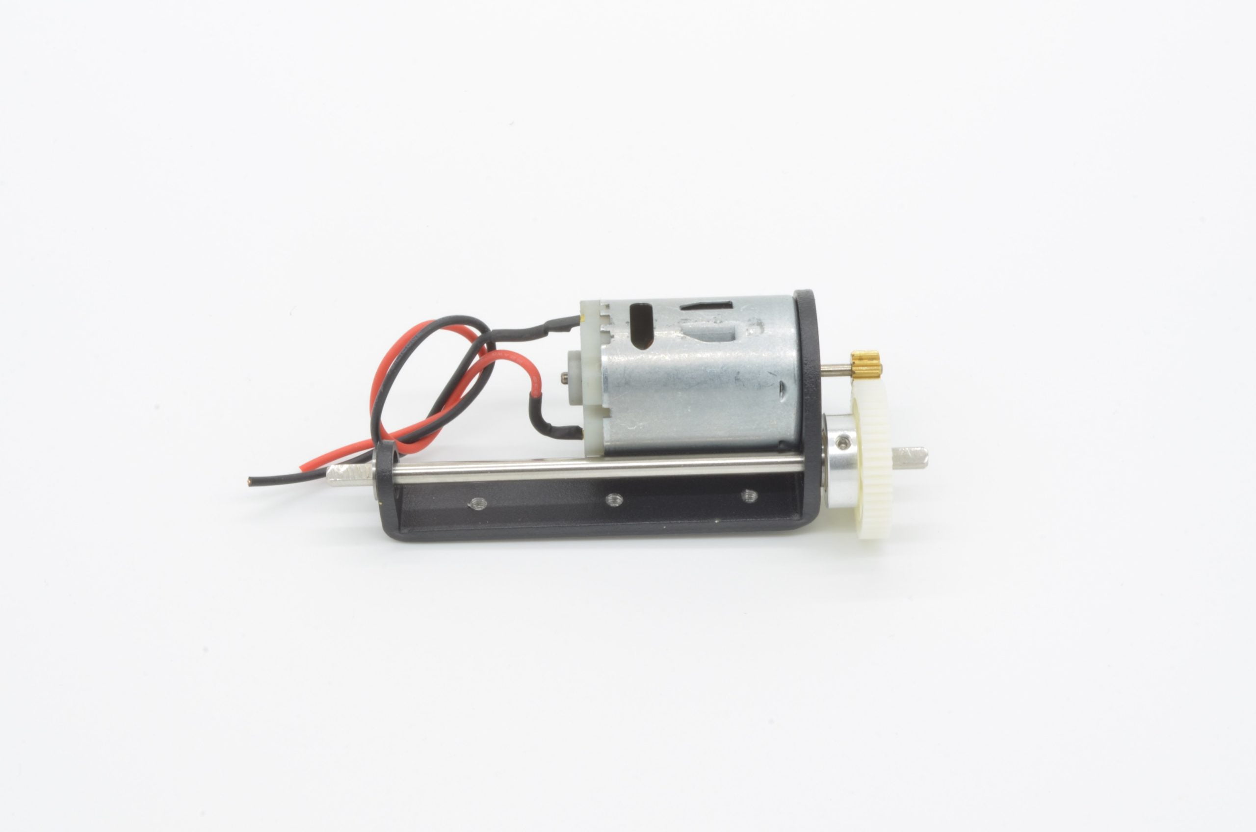
Slide the gear on to the shaft and align it with the motor gear. You will want to ensure the set screw is on the flat side of the shaft. Once it is aligned, carefully tighten the set screw using the small Allen key included with the kit.
Finally, we are going to install the wheel hubs. The two hubs are different lengths so be sure to install them on the correct sides. The shorter hub is used on the side with the gear, while the longer one is used on the opposite side.
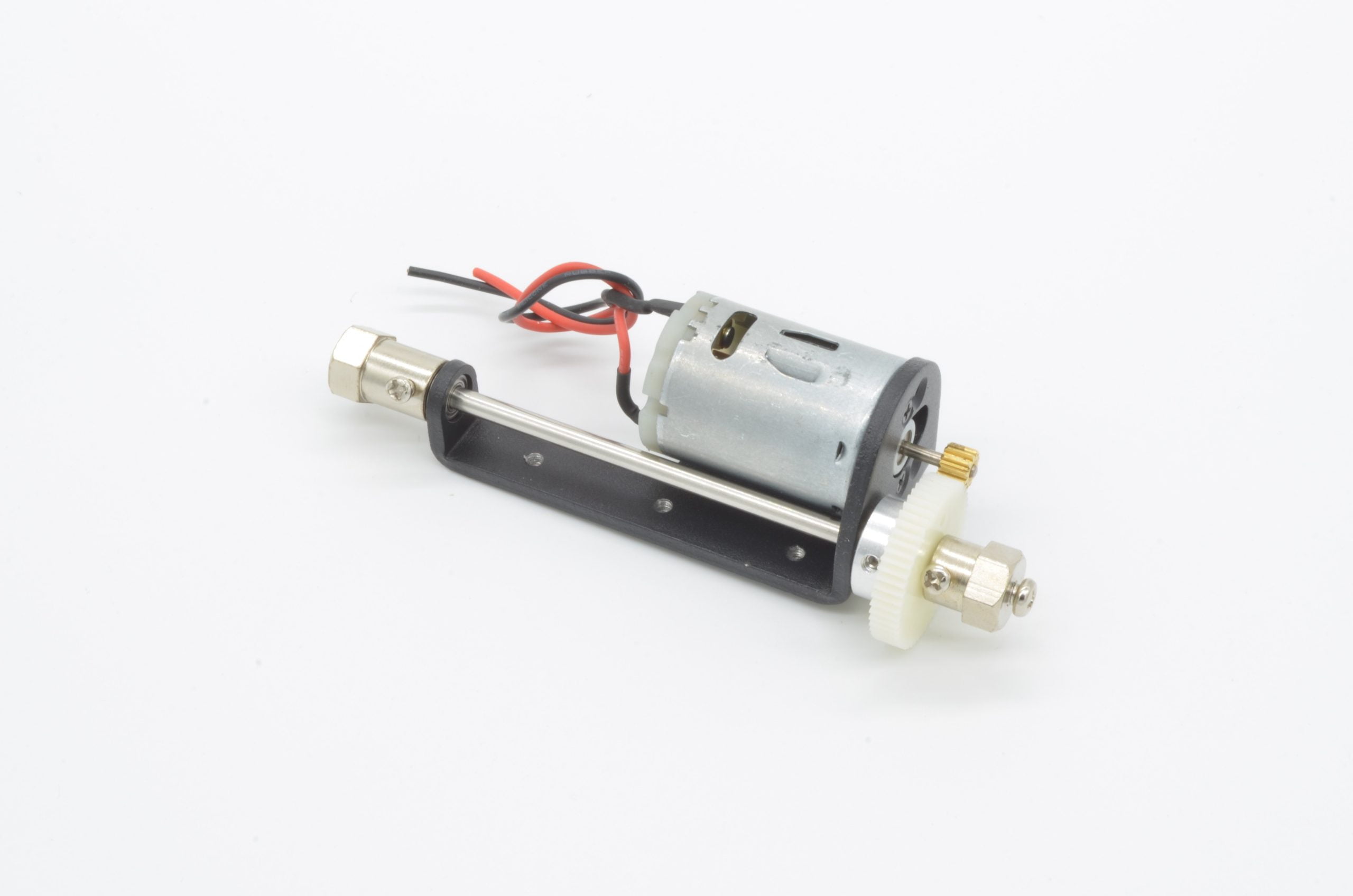
Your assembled motor and axle should look just like the photo.
Caution:We found the screws used to set each hub to the axle are best tightened with a larger Philips screwdriver (PH2). The included screwdriver is a bit too small and may strip the head out of the screw.
15%
Step 3 - The Knuckles & Front Stub Axles
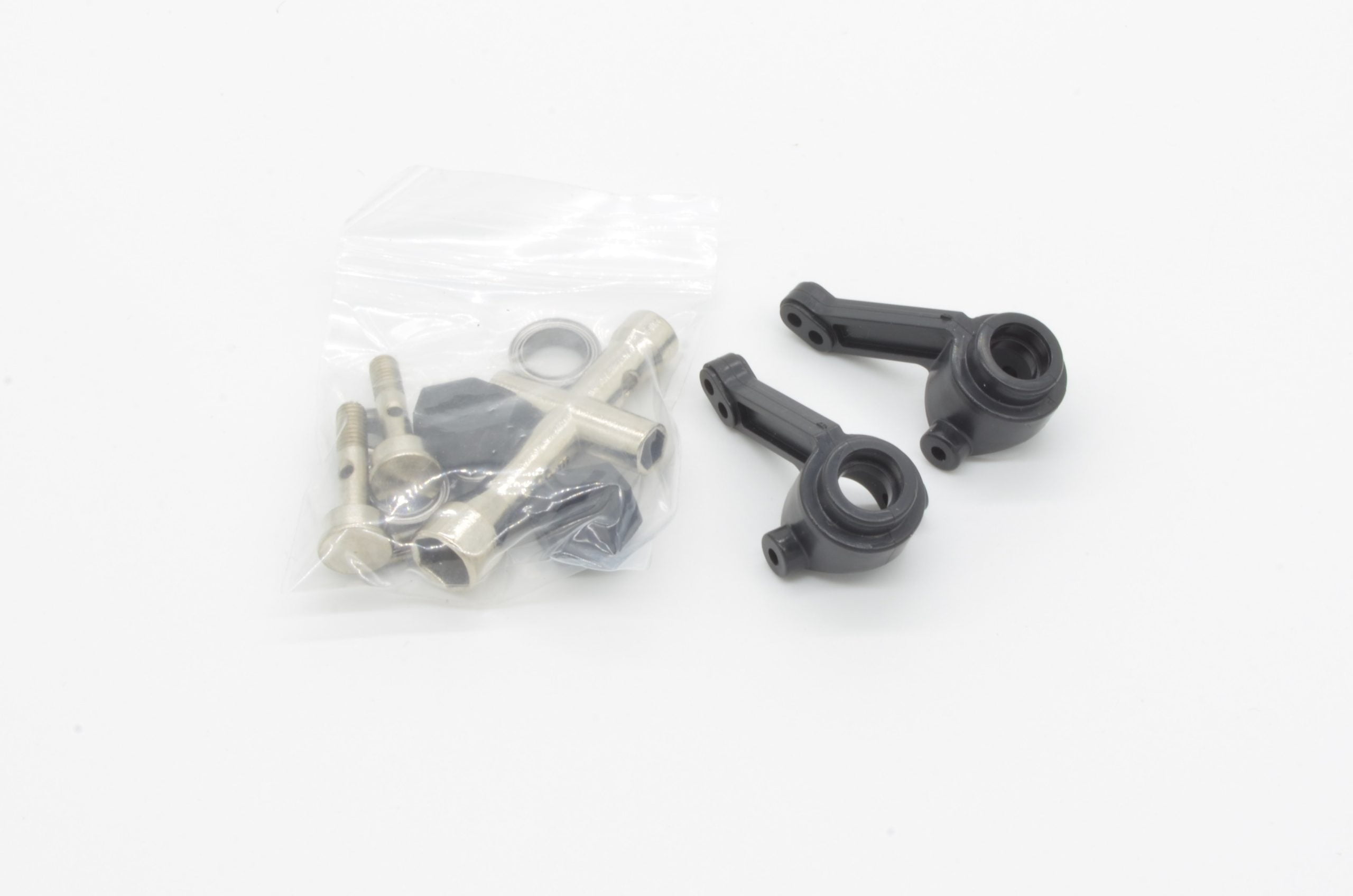
The next step will be the front steering knuckles and stub axles. These are the components that hold the wheels and allow the wheels to turn. We will need the two plastic molded knuckles and the bag containing the stub axles, inner and outer bearings, locking pins, and front wheel hubs. All of the bearings, pins and hardware should be in one bag.
Since there is a steering knuckle on each side, you will need to follow these steps twice. Start by getting all of the components organized.
The knuckle holds the inner and outer bearing while the stub axle presses through and is held in place with a metal pin, which is held in place by the wheel hub. If this sounds complex, don’t worry – it is, and we will go through it step by step.
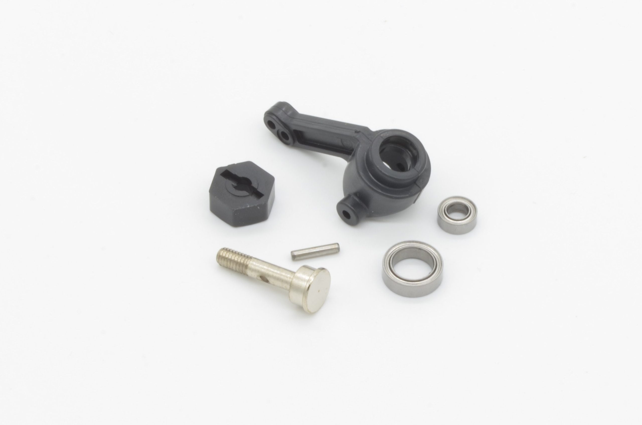
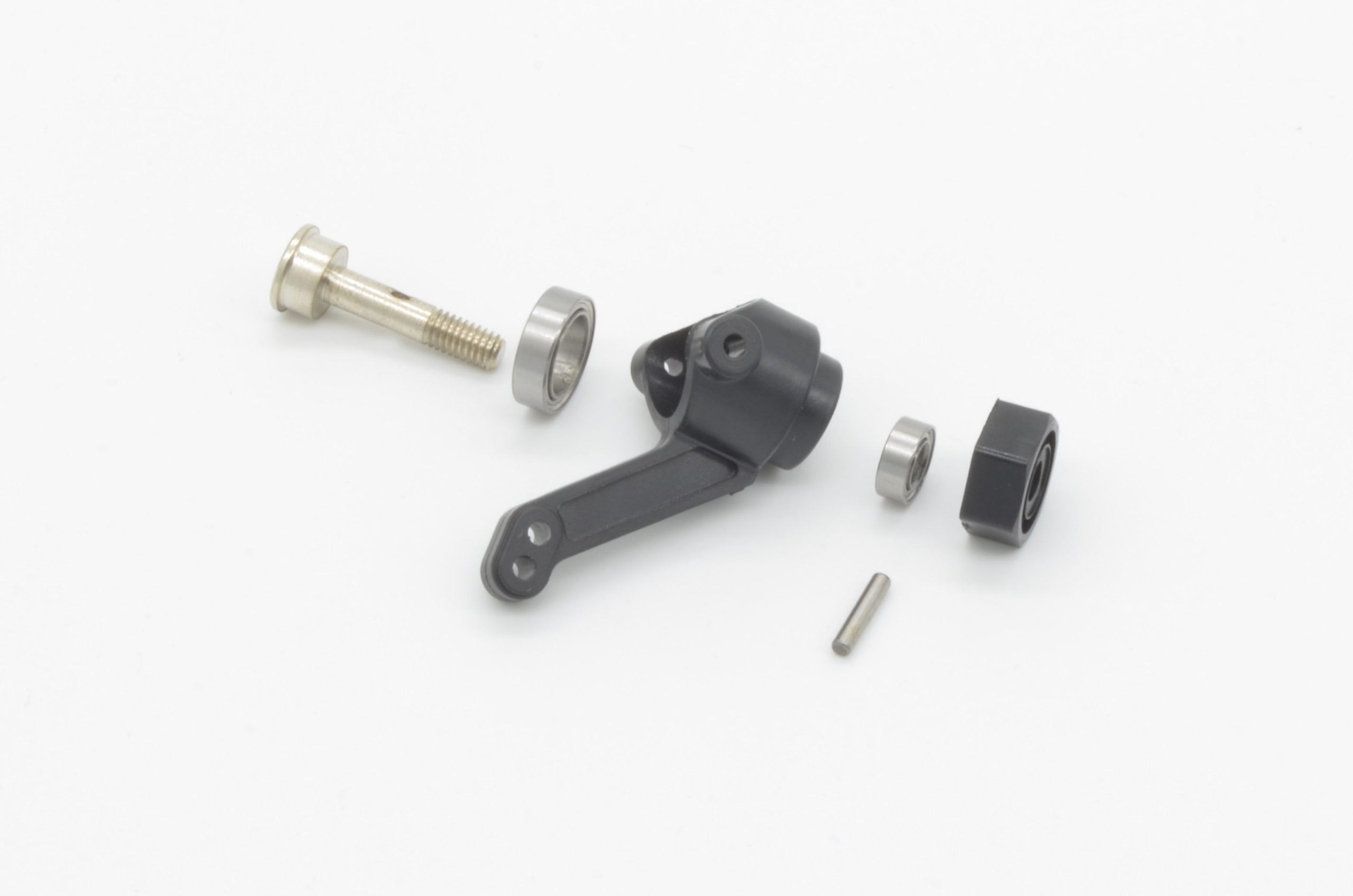
First we will press the inner bearing into the knuckle. Make sure it is aligned and squared to the housing and press it all the way in.
Next, line the outer bearing in the front of the knuckle and press it in.
Now we will press the stub axle through from the back. It may take a little extra force to ensure the inner bearing pressed in far enough to allow the locking pin to be inserted. The locking pin should not be resting against the face of the bearing, it will need to spin freely.
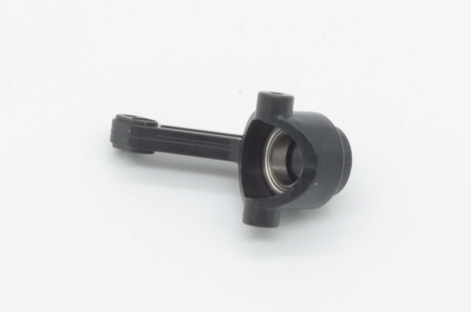
Finally, slide the wheel hub onto the end of the stub axle being careful to align the pin with the retaining lines in the wheel hub. Once completed it should look like the photo. Now repeat once more for the other side!
23%
Step 4 - Starting On The Chassis
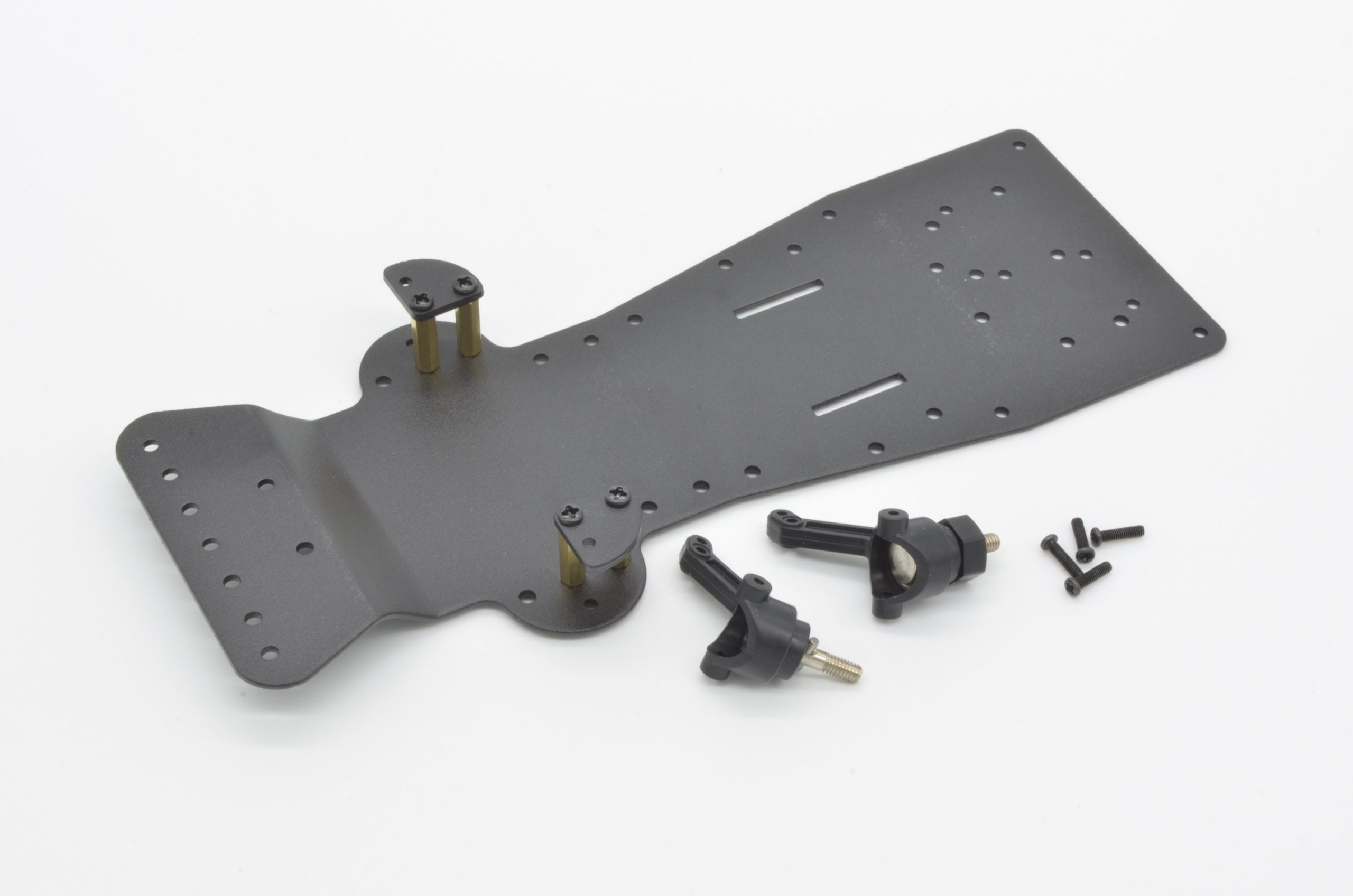
It is time to start working on the chassis itself. We are going to start with the mounting points for the steering knuckles we just built in the last step. Start by finding the main chassis, 4 x 22mm Brass Standoffs, 8 x M3x8mm screws, and the two top caps.
Ensure the chassis is in the correct orientation – the front bumper mount should curve up and away from the base. Start by placing screws through the correct holes in the base and thread on the standoffs. Next, align the caps and lightly thread the screws. You will need a little flexibility to get the knuckles slide in, so don’t fully tighten them just yet!
30%
Step 5 - Installing The Knuckles
Continuing where we left off in the last step, we will now add the knuckles. We will need both of the assembled knuckles from Step 3 and 4 x M2x10mm screws. In the next few steps, we will be using these M2 screws to cut threads into the smaller holes in the knuckles.
Important: install the knuckle in the correct orientation for each side! Line up the top hole of the knuckle with the remaining hole in the piece we just attached in the last step. These will take a bit of effort to get through, so be sure to use the correct sized screwdriver to avoid stripping the head of the screw.
Assembly Note:Do not over tighten these screws, they will be acting as pivots and will need to allow the knuckle to rotate.
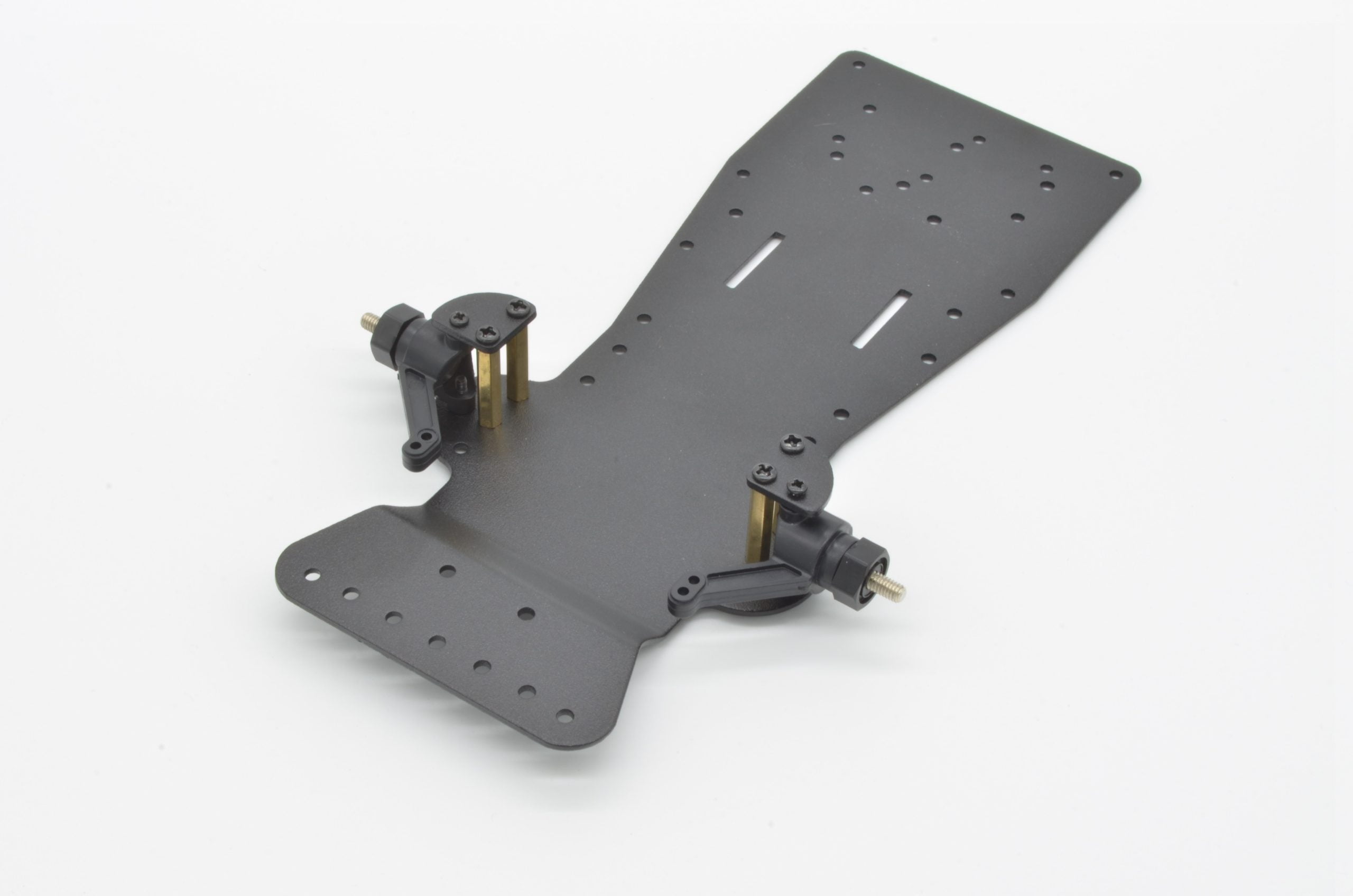
Once the top has been installed, repeat the process for both sides on the bottom. The end result should look like the photo.
The standoff screws from the previous step can now be fully tightened. The knuckles should rotate freely, but there should be minimal vertical movement
38%
Step 6 - Installing The Lower Tie Rod
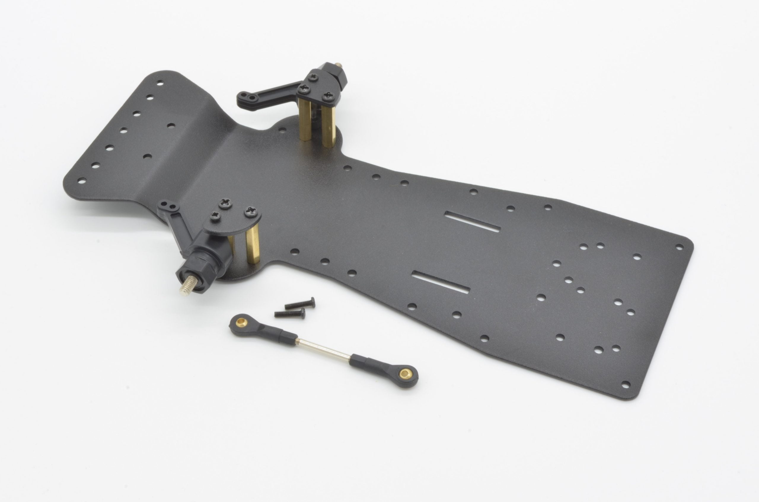
To create the steering rack, we will first need to connect the knuckles to one another. This is done with a tie rod. The kit has two tie rods, for this we will be using the larger of the two. It will be attached using 2 x M2x10mm screws.
Tie rods can be adjusted in length by twisting them to unthread the middle bar. This is one parameter that is adjusted during a wheel alignment on your car. Imagine looking down from directly overhead – the toe is the amount the front of the wheels point towards (or away) from each other.
We want to have very minimal toe angle, so get both wheels lined up facing forward as straight as possible and adjust the tie rod to match the length as close as you can.
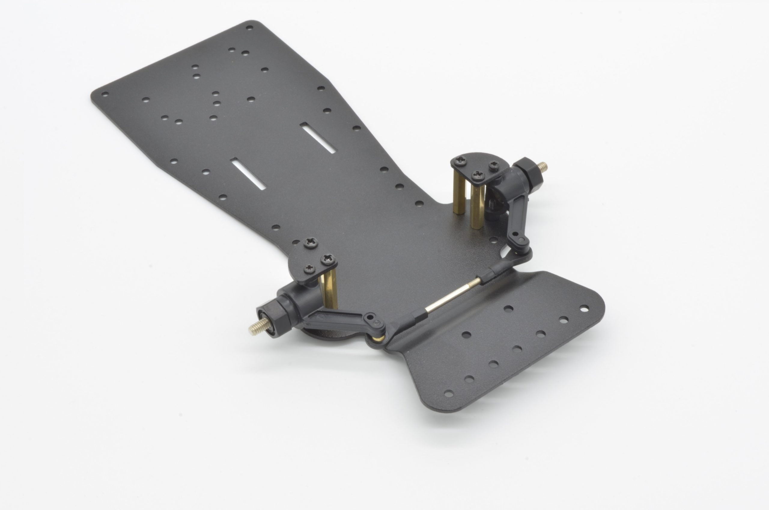
Since we are installing this tie rod below the knuckles, it is easier to flip the chassis over and install it. The end result should match the photo.
46%
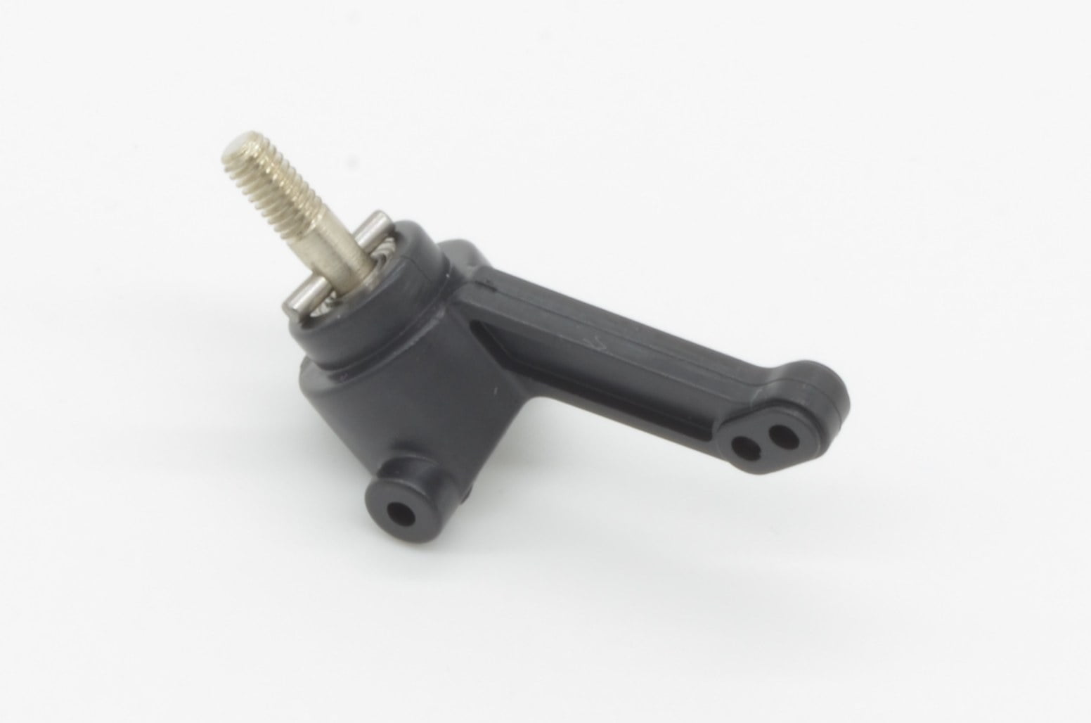
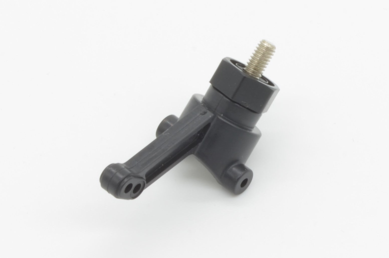
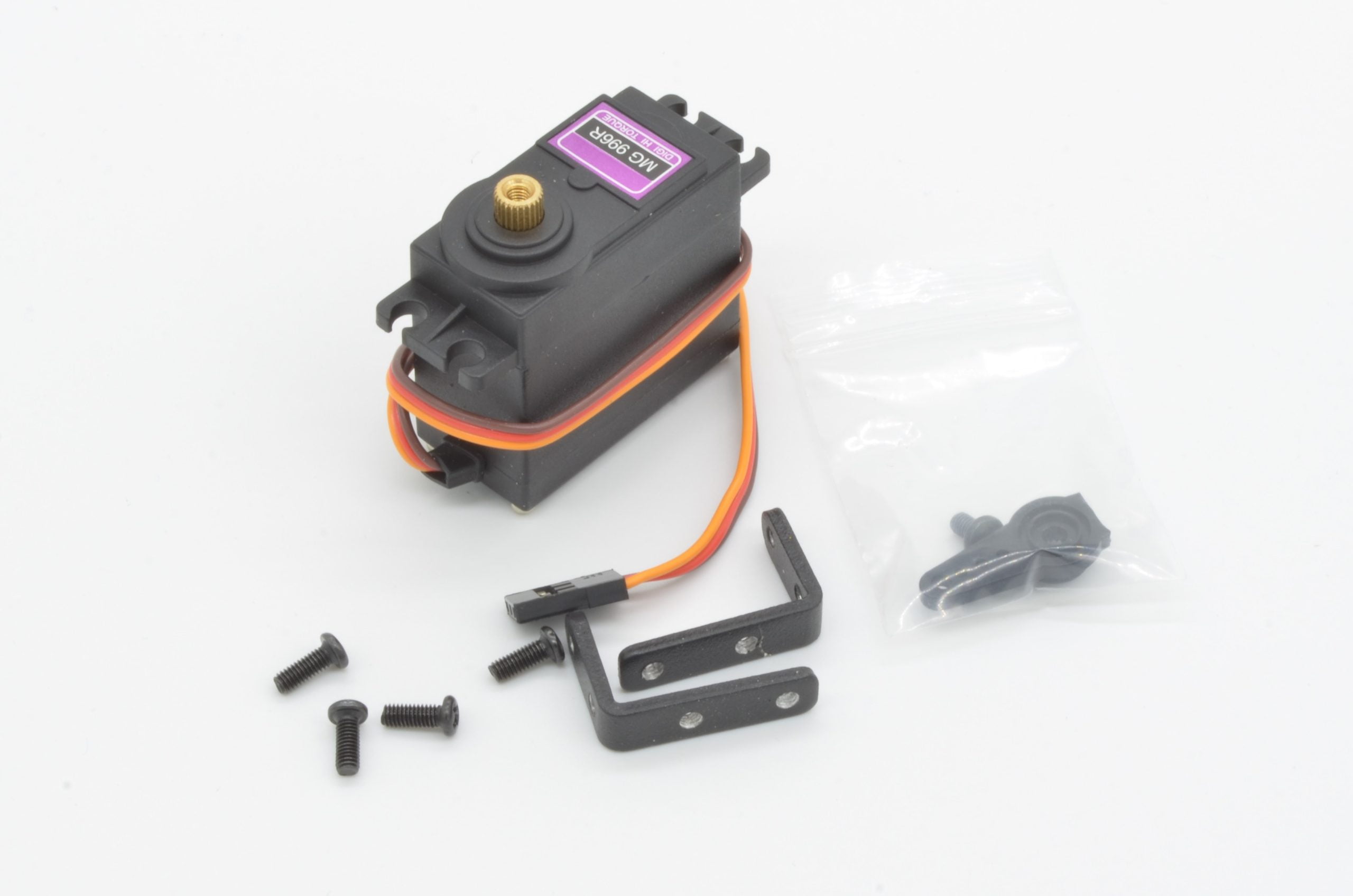
Step 7 - Preparing The Steering Servo
Now we will get the steering servo ready for installation. The servo will need to have its mounts installed as well as a servo horn to help connect to the steering rack. We will need the small bag of servo parts, 4 x M3x8mm screws, and the two mounting brackets.
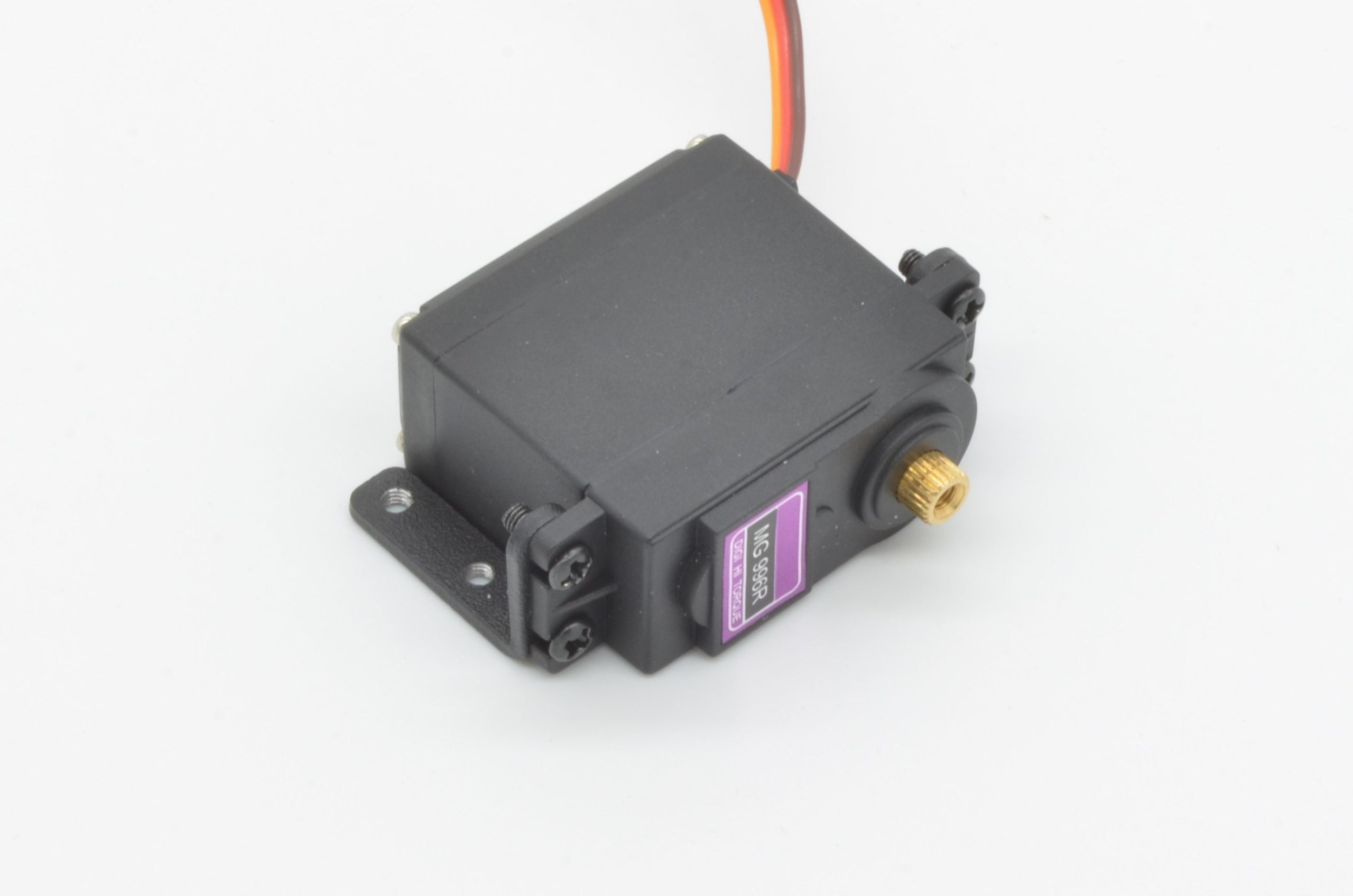
Start by installing the mounting brackets and ensure the servo orientation matches that of our photo. The shorter side of the “L” bracket mounts to the servo, while the longer side is used to bolt it to the frame. It is best to leave these untightened until the assembly is mounted to the chassis – it will ensure the holes line up without too much trouble on the chassis!
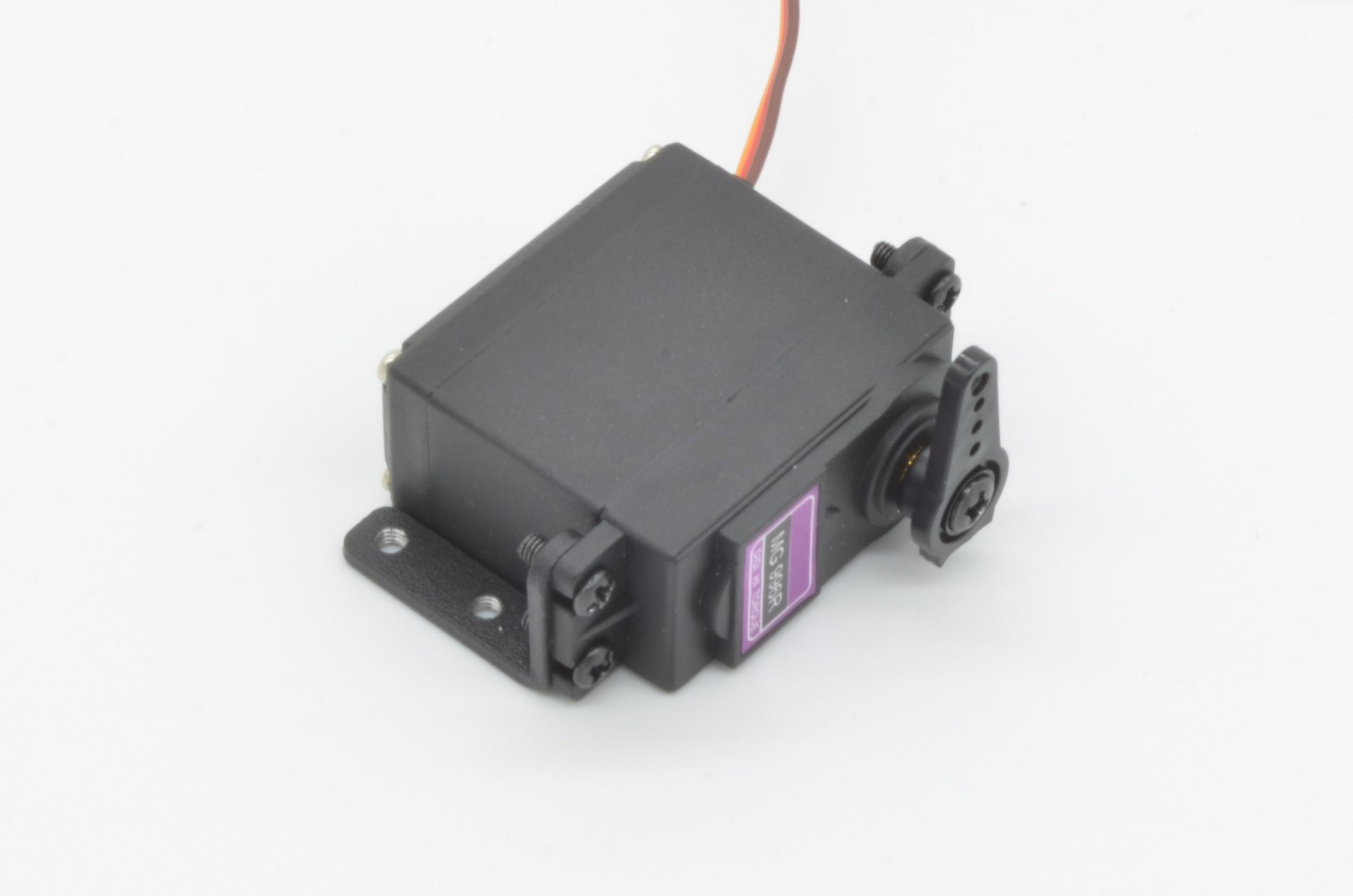
Finally, we will need to mount the servo horn to the servo. Pay careful attention to the orientation of the servo and the horn.
Caution:Before powering up your project for the first time, it is a good idea to test with your servo horn disconnected. If there are any errors in your code, or the servo horn is not in the correct orientation, it could save you damaging a servo (or other components)
54%
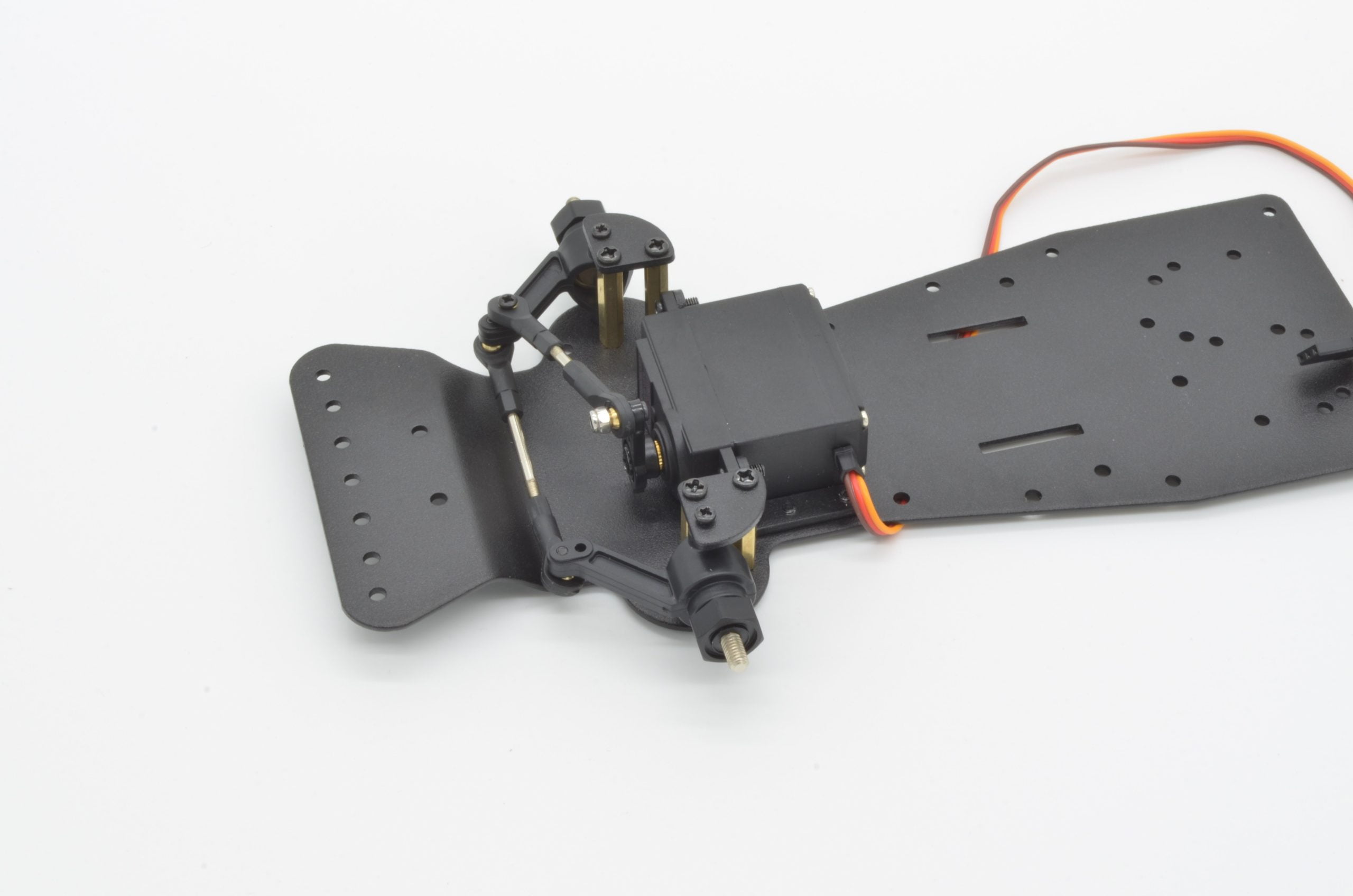
Step 8 - Installing The Steering Servo
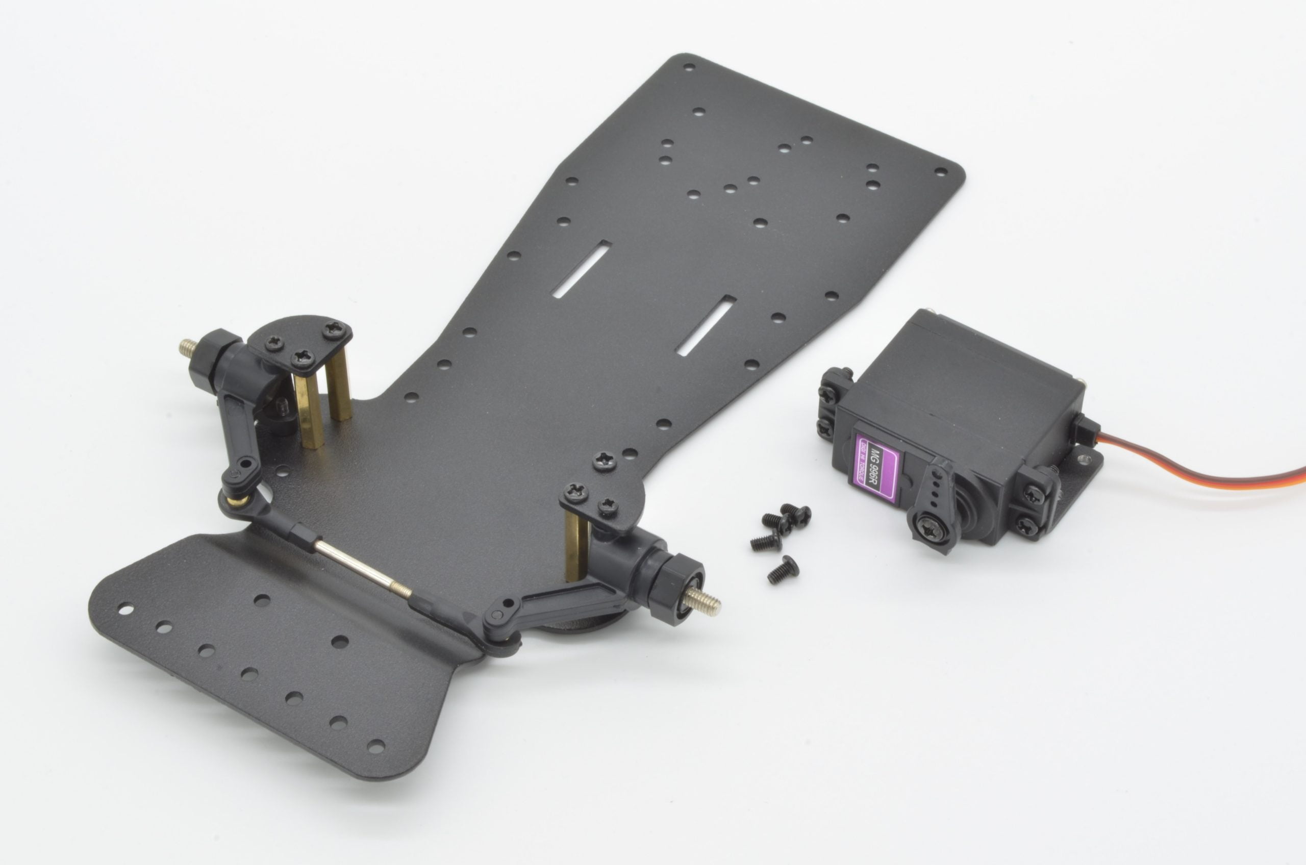
It is time to install the servo assembly to the chassis. We will need 4 x M3x5mm and the servo assembly from the last step.
The servo brackets will align with the two holes on each side (immediately behind the steering mounts). The servo mount has M3 tapped holes, so carefully thread each through. Once all of the screws are started, tighten all 4 screws, followed by all 4 on the servo that we left untightened before. The servo should not move – once completed it should match our photo.
61%
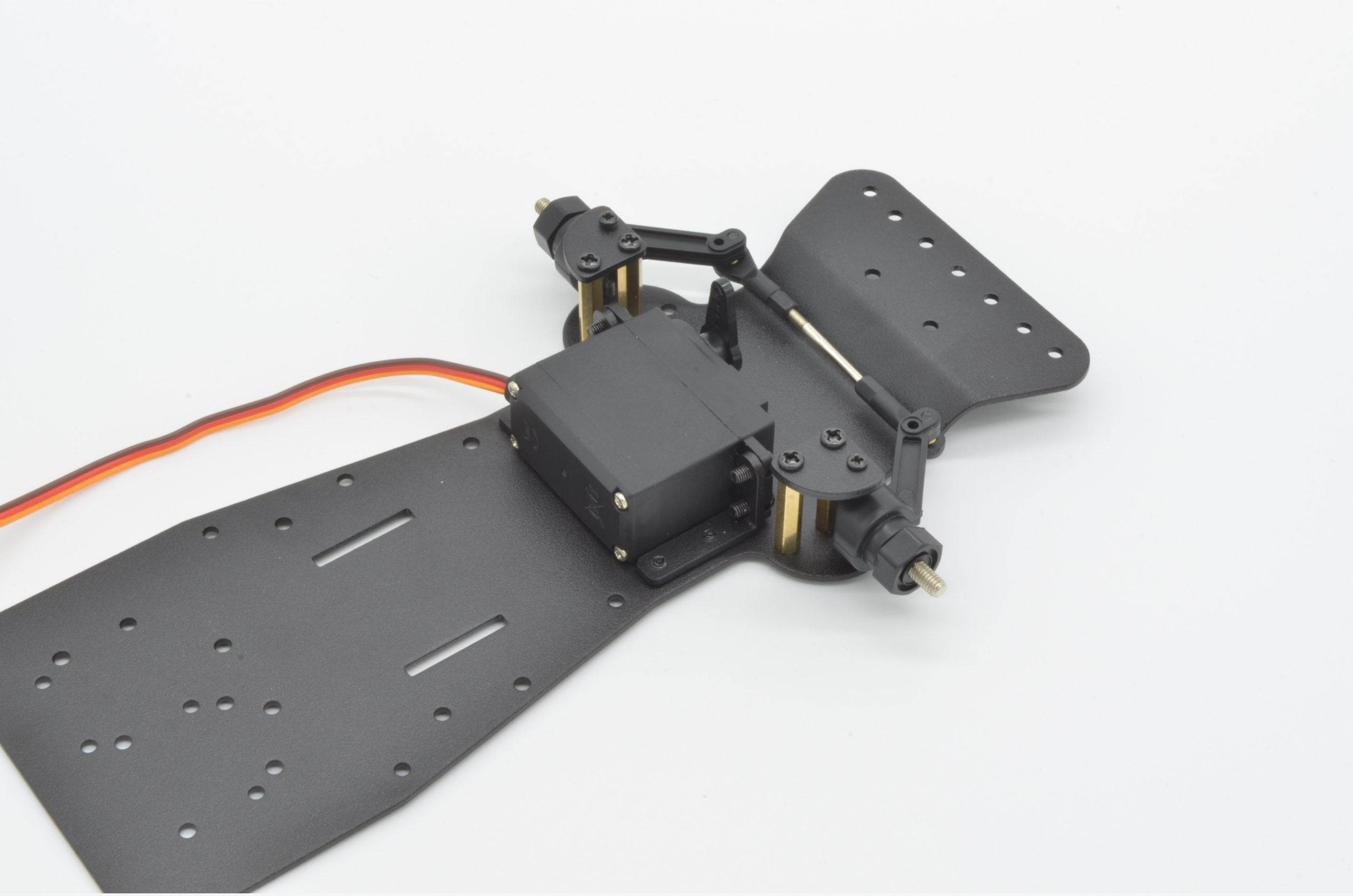
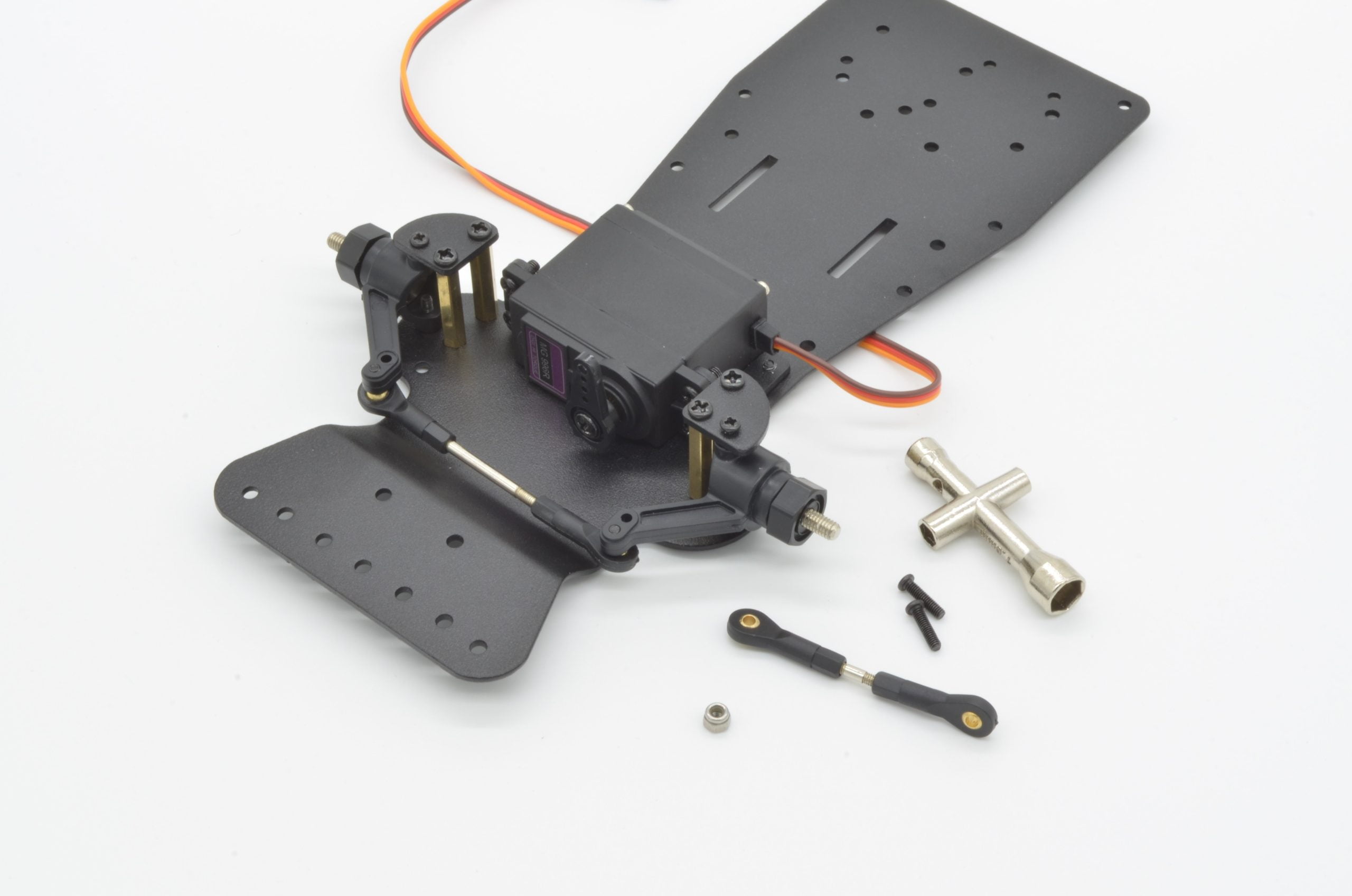
Step 9 - Connecting The Upper Tie Rod
The upper tie rod connects the servo to the steering rack to the servo. We will need 2 x M2x10mm screws, 1 x M2 nut, and the remaining tie rod. The included nut driver tool will also be required.
To start, orient the tie rod as we have in the photo. You will want the ends offset by 90 degrees from one another. The length of this rod can be adjusted as well, so if you find it too short, it is a good time to make that adjustment. Ideally the wheels should point straight with the servo horn vertical once this is installed.
Insert one of the M2 screws through one end of the tie rod and thread it into the remaining hole on the steering rack (the right side of the steering rack when facing forwards).
Now, insert the other M2 screw through the hole in the servo horn and then through the tie rod. The M2 Nut can now be threaded onto the screw, completing the assembly. Do not tighten the nut too much, it should be able to rotate without binding, but not be so lose that it slides around.
69%
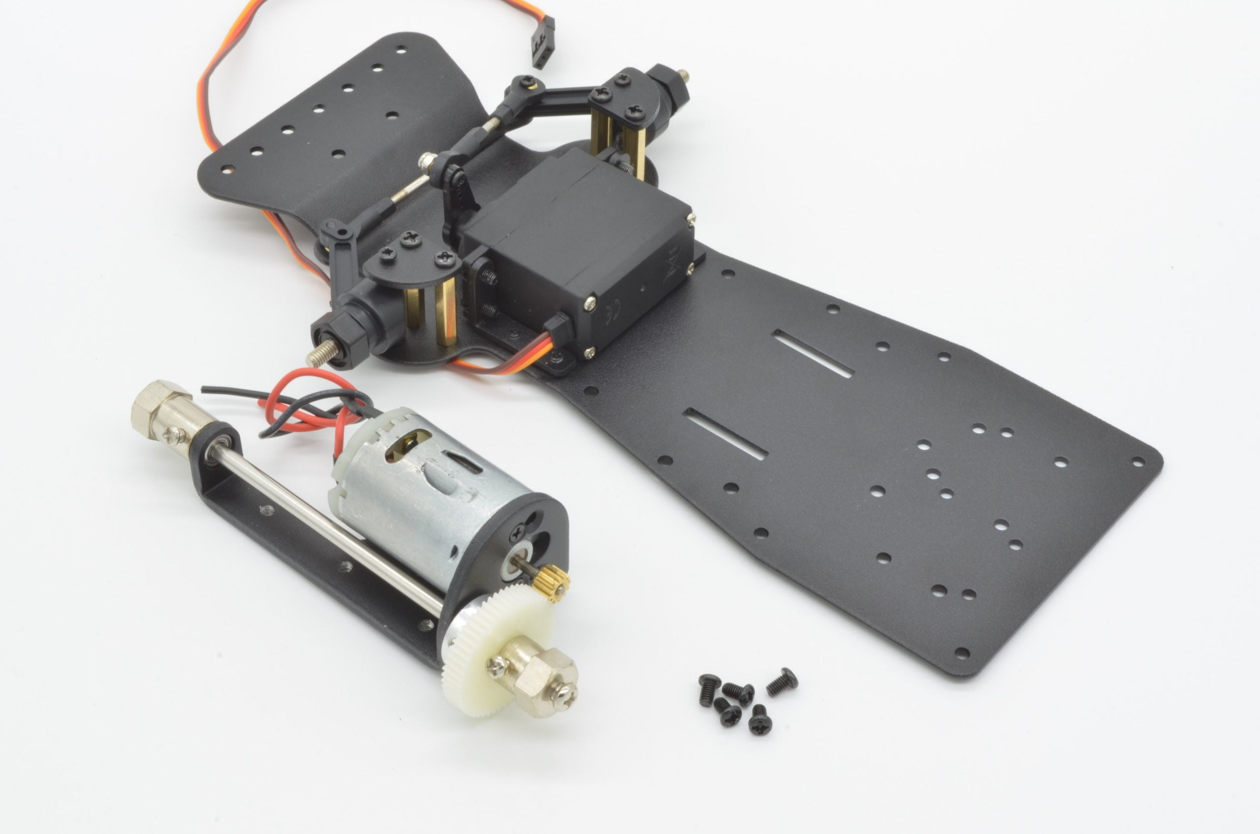
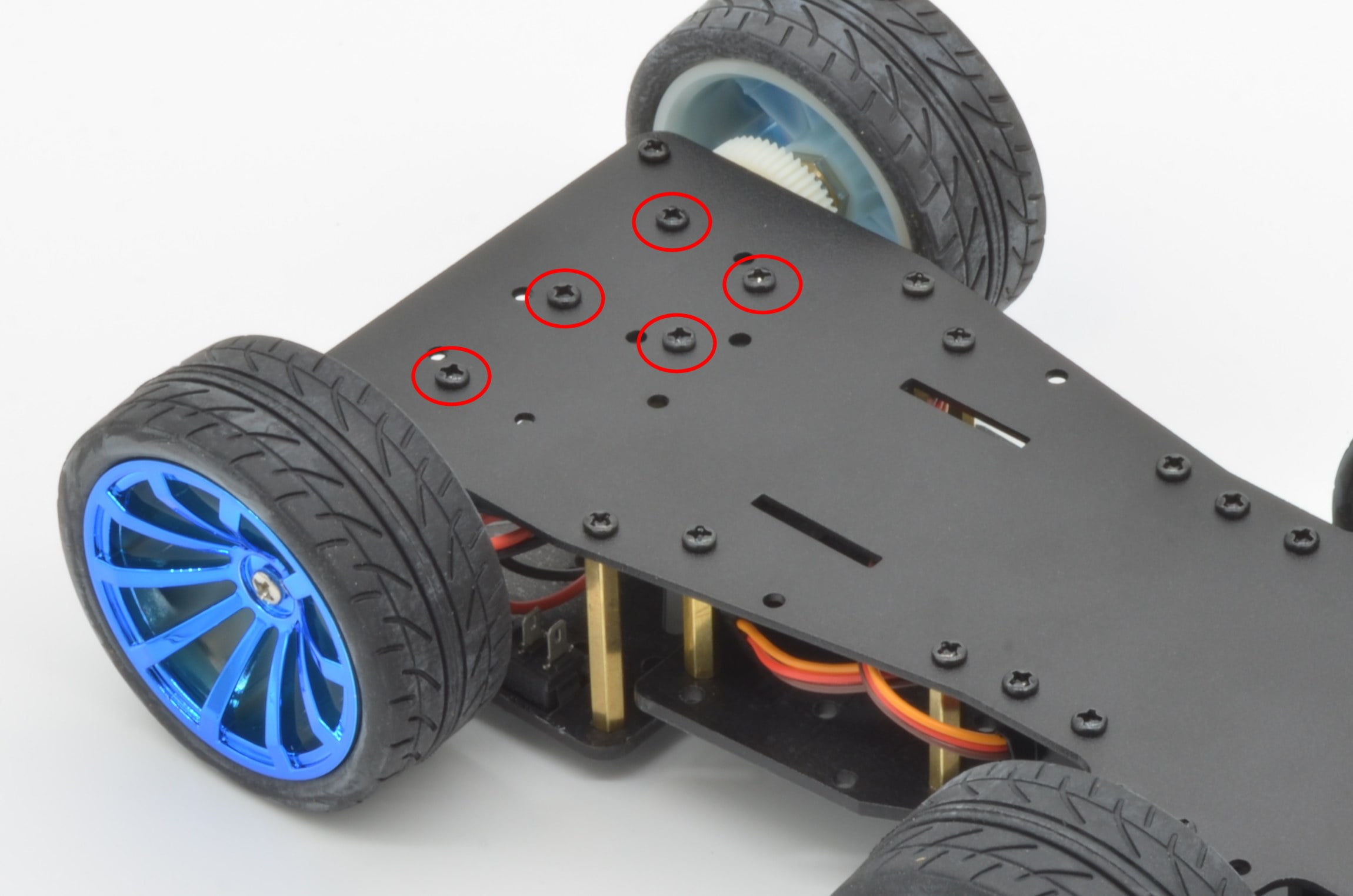
Step 10 - Mounting The Motor And Cover Plate
It is time to attach the motor and the cover plate. To start, we will need 5 x M3x5mm screws and the completed motor assembly. The motor mounts to the base with 5 screws that are inserted from the bottom of the chassis. The driveshaft will be oriented towards the back of the chassis.
With the motor assembly roughly held in place, flip the chassis over and align the holes as indicated in the photo. Start each screw, but do not tighten them until all 5 are threaded. Once all 5 are started, tighten each screw down. This component should not move once tight.
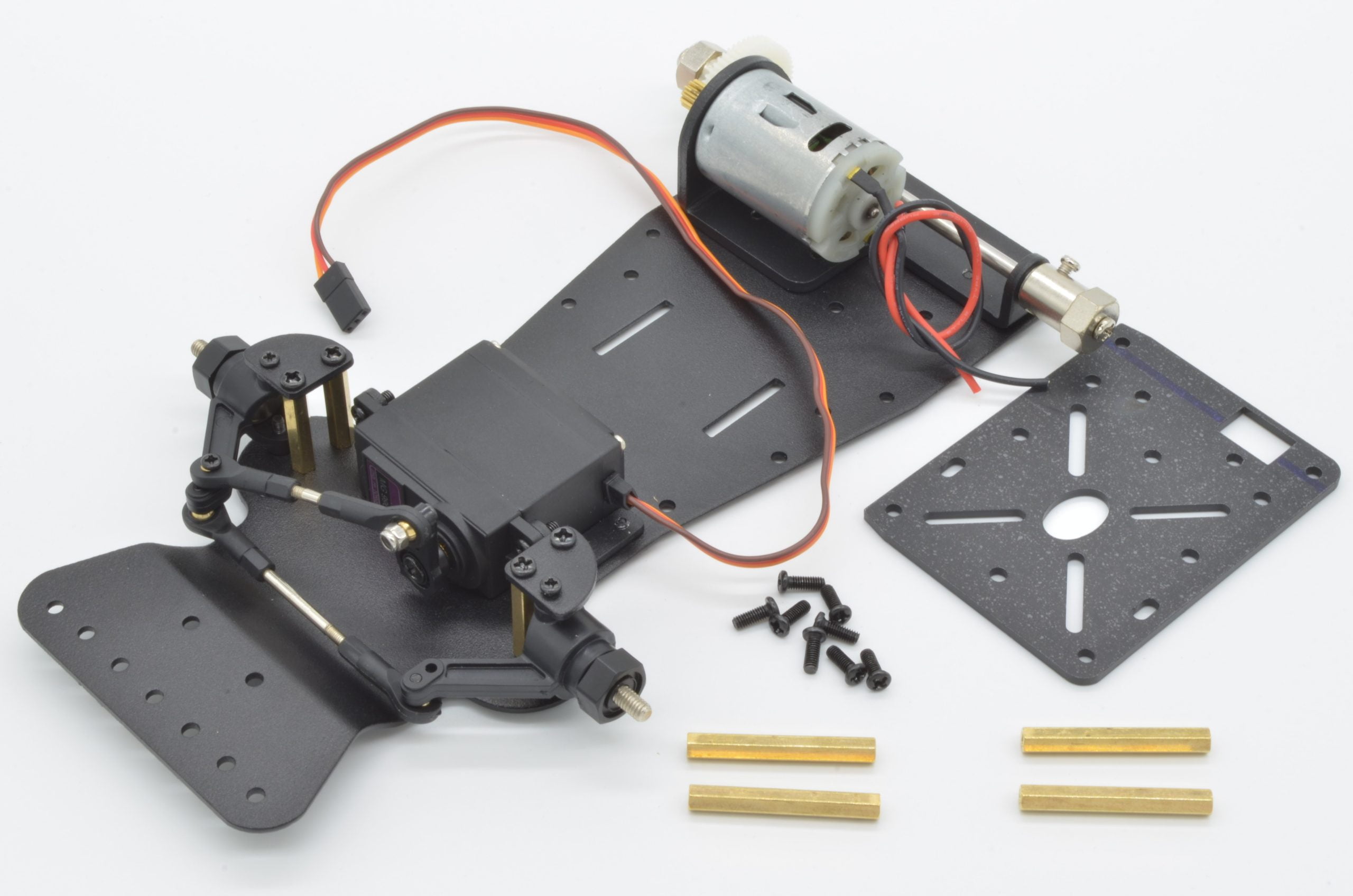
Next, we will install the motor cover / rear mounting plate. We will need 4 x 35mm Standoffs, 8 x M3x8mm screws, and the rear cover plate. This is a great place to mount electronics, sensors, and other parts!
We will be using the 4 corner holes of the cover plate, so start by placing screws through the cover plate from the top (the top orientation can be seen in the photo). Thread but do not fully tighten the standoffs to each of the screws.
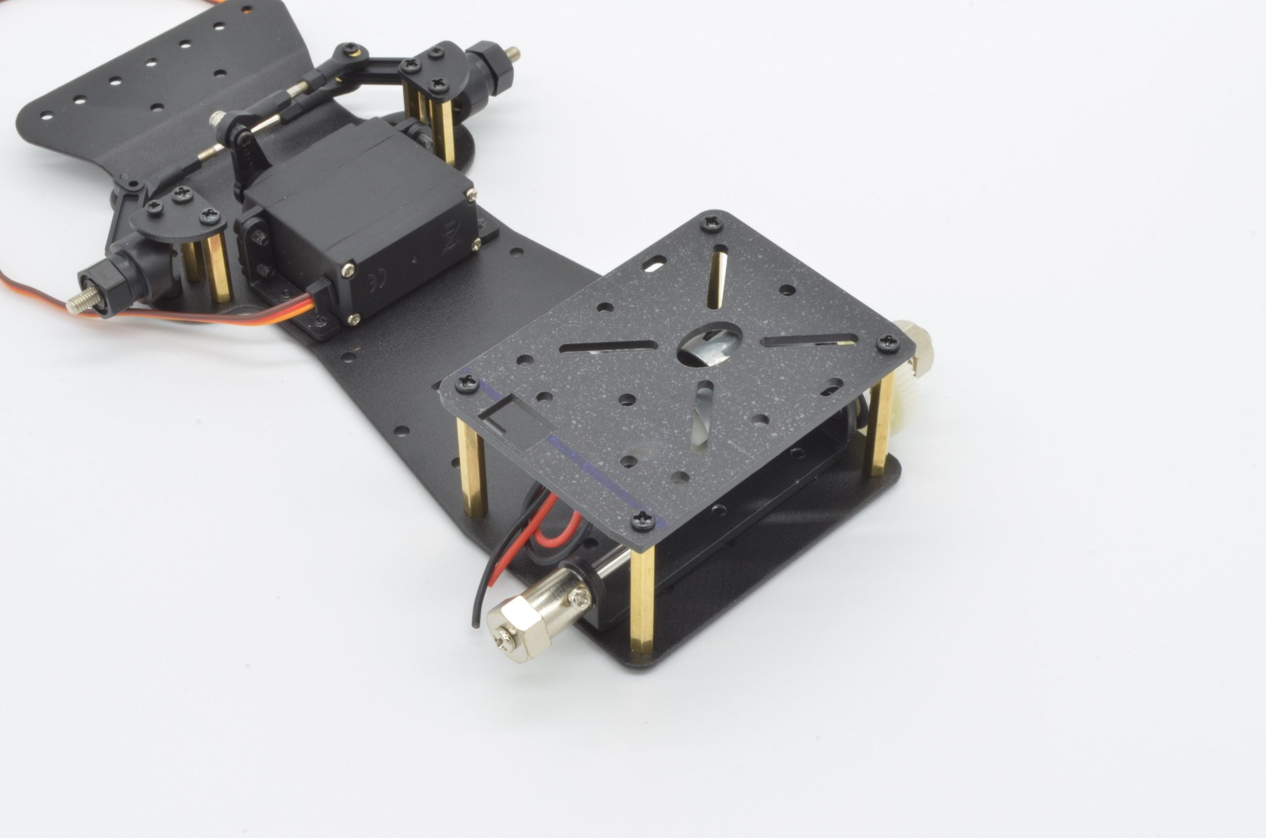
Finally, line the standoffs up with their respective holes in the chassis and insert a screw through from the bottom. Tighten these screws to the standoffs and then tighten the previous 4 screws to complete the assembly.
77%
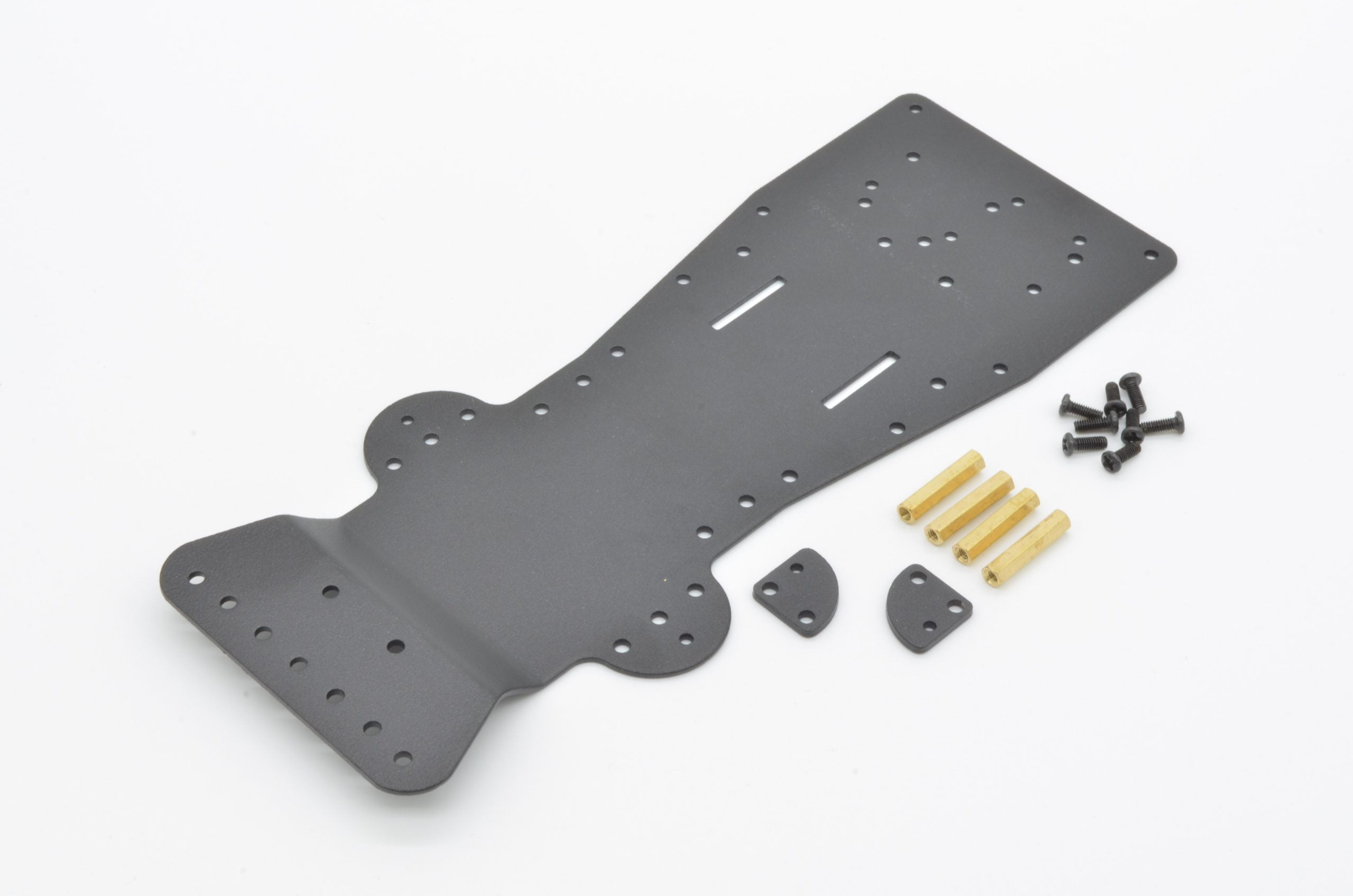
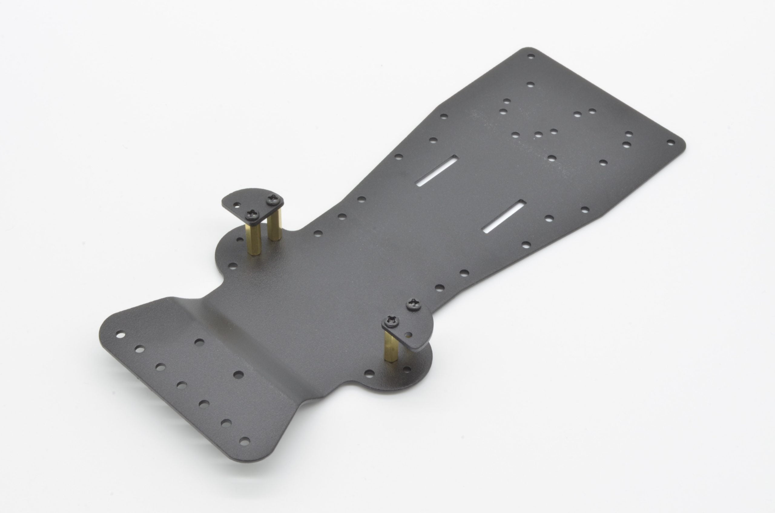
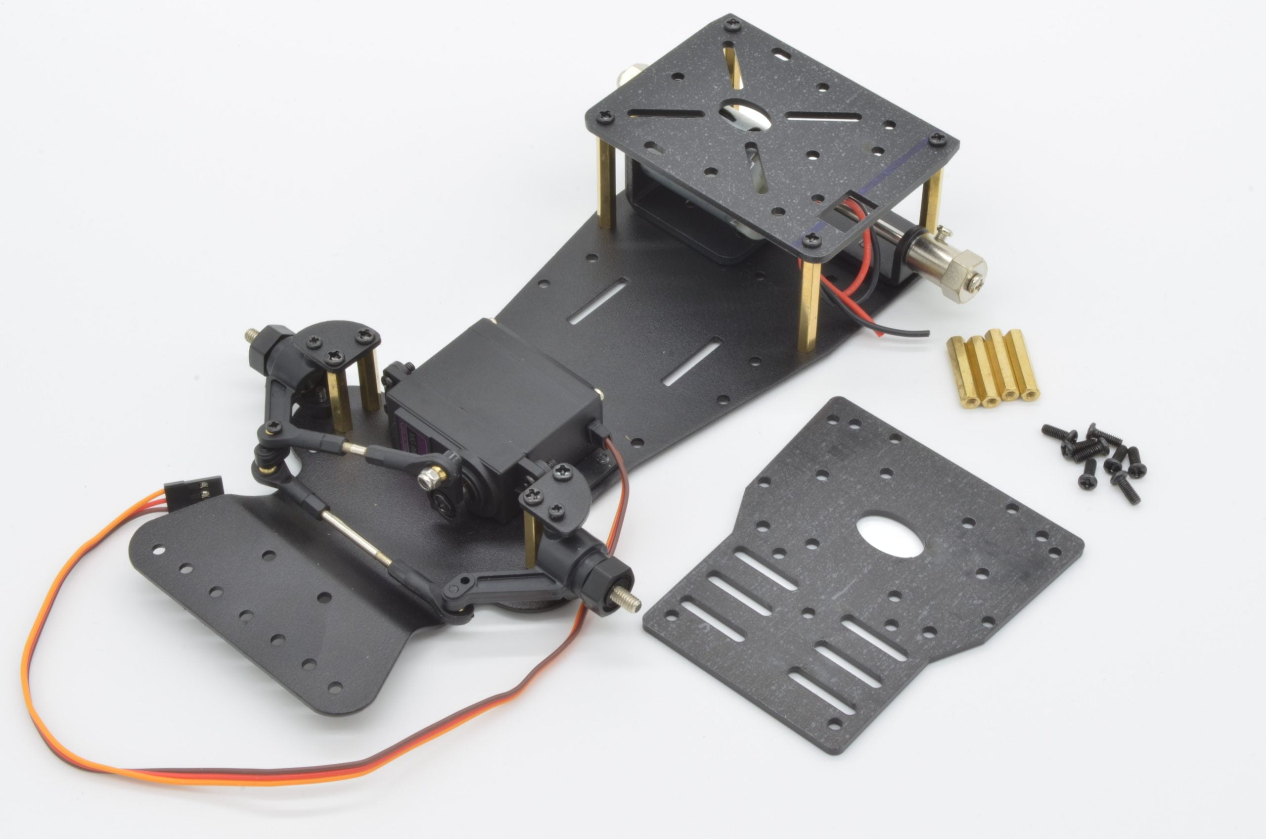
Step 11 - Installing The Middle Cover Plate
The middle mounting plate is another place to install electronics. The mounting holes will line up with a Raspberry Pi or Arduino. The ABS plastic is easy to drill if additional holes are required.
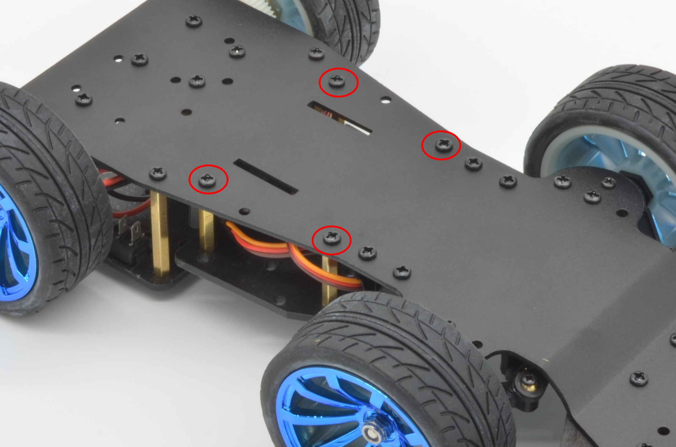
We will need 4 x 22mm Standoffs, 8 x M3x8mm screws, and the middle mounting plate. Start by placing the screws through the bottom of the chassis in the indicated holes. Once again, do not fully tighten these until we have the plate attached.
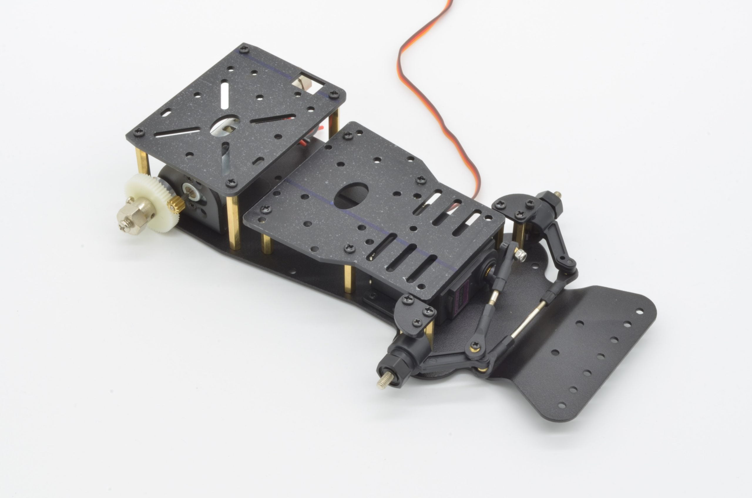
Next, place each screw through the corresponding hole on the mounting plate and tighten each screw down. The first four screws can now be fully tightened. The end result should match our photo.
85%
Step 12 - Installing The Bumper
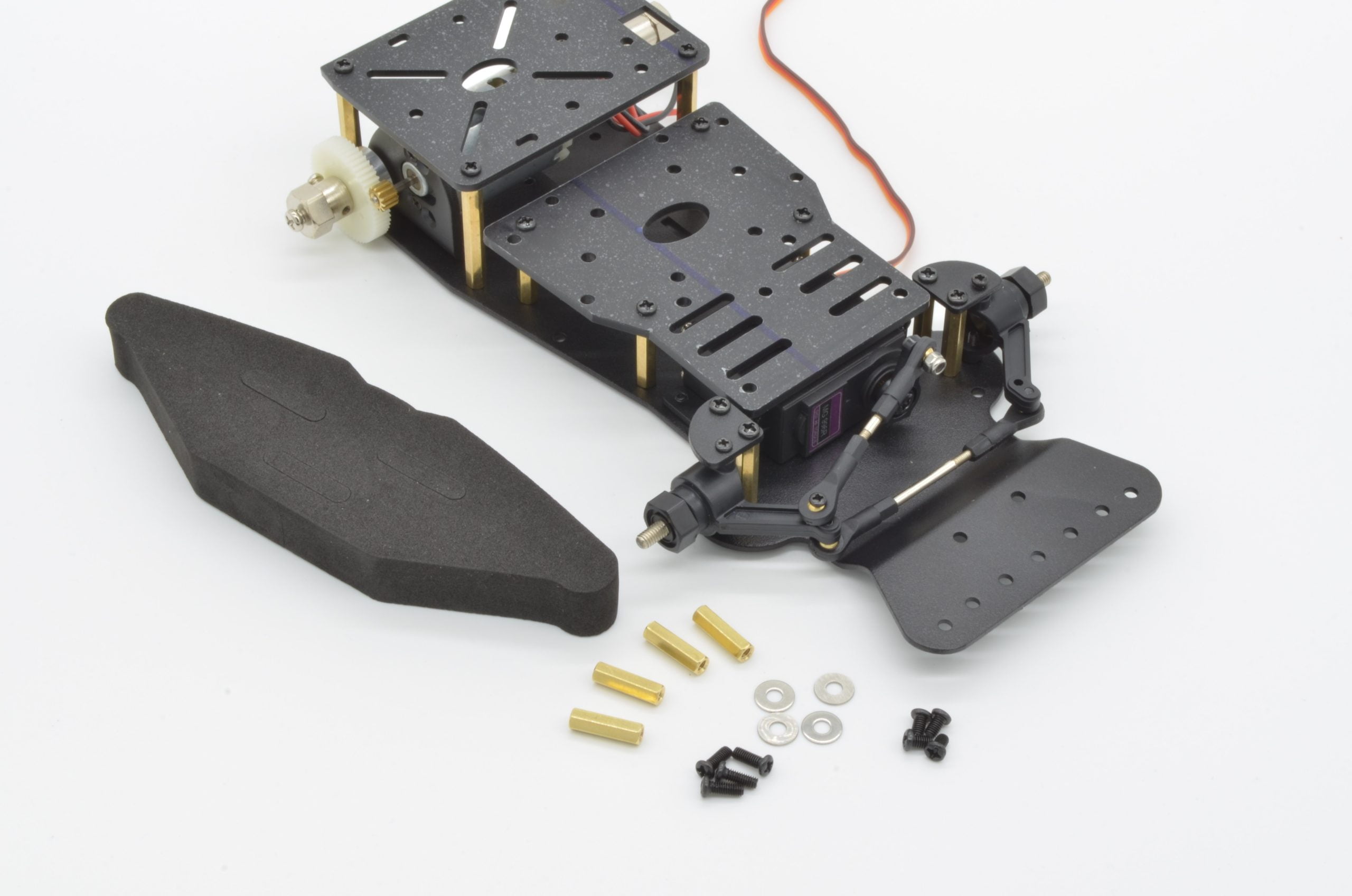
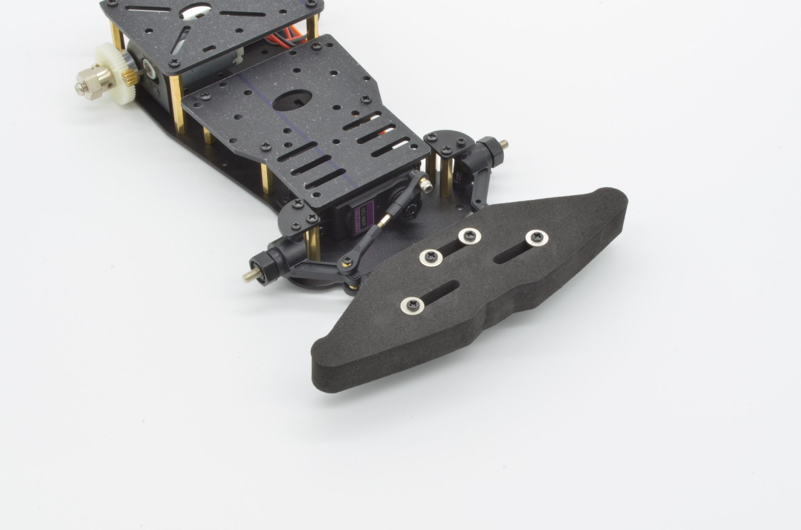
The final piece of the chassis itself can now be attached – the bumper! To attach it we will need 4 x M3x8mm screws, 4 x M3x5mm screws, 4 x 16mm standoffs, 4 washers, and the bumper. This bumper is made of a high density foam – so start by removing the cut-outs in the bumper foam to make room for the hardware.
With the chassis upside-down, we will use the M3 x 8mm screws and insert them through the indicated holes. Attach a standoff to each of the screws and tighten them down. The standoffs will act as a guide to hold the bumper in place.
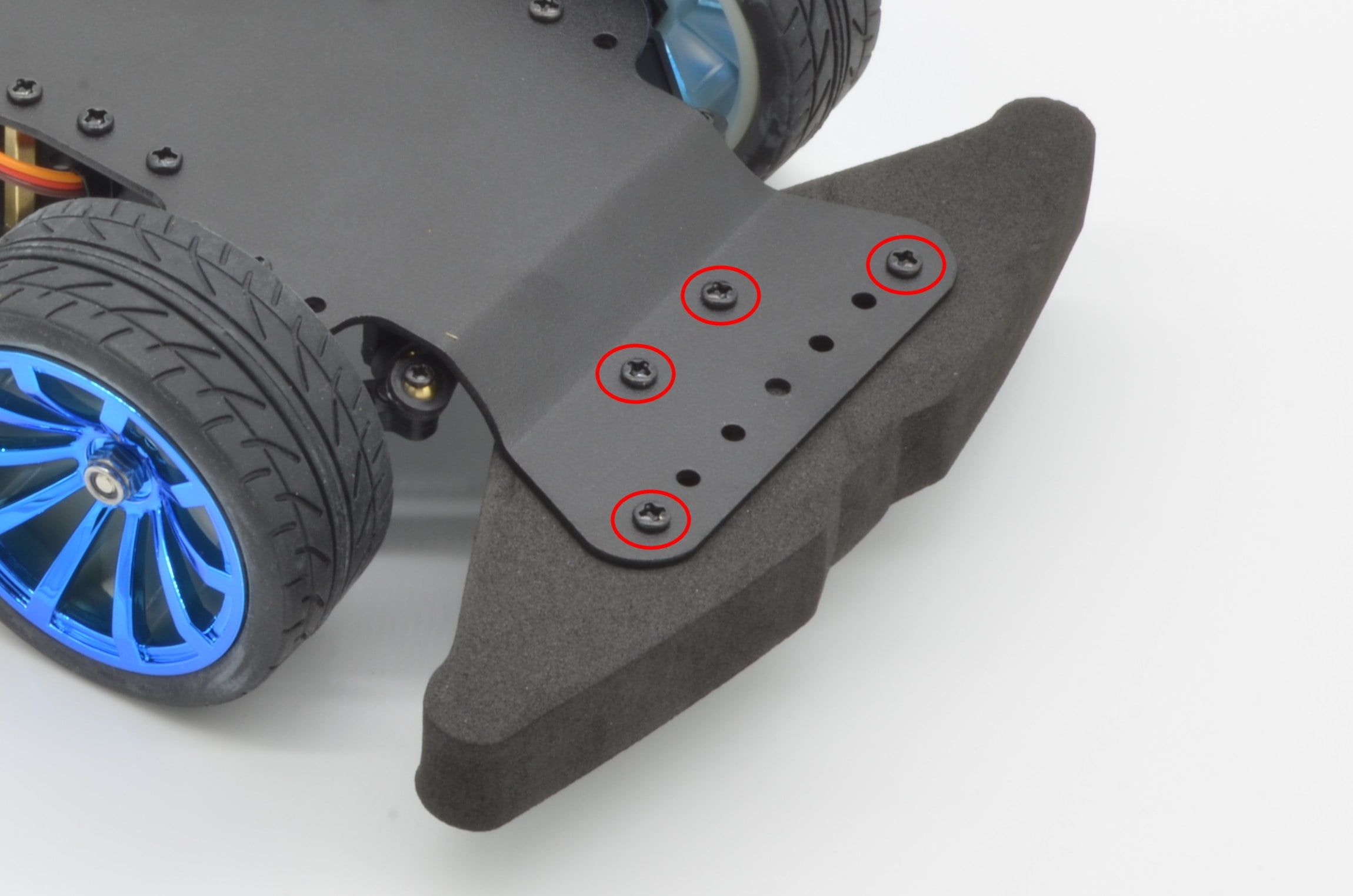
Slide the bumper down over the standoffs and, with a washer, use each of the M3 x 5mm screws to attach the bumper as shown in the photo.
92%
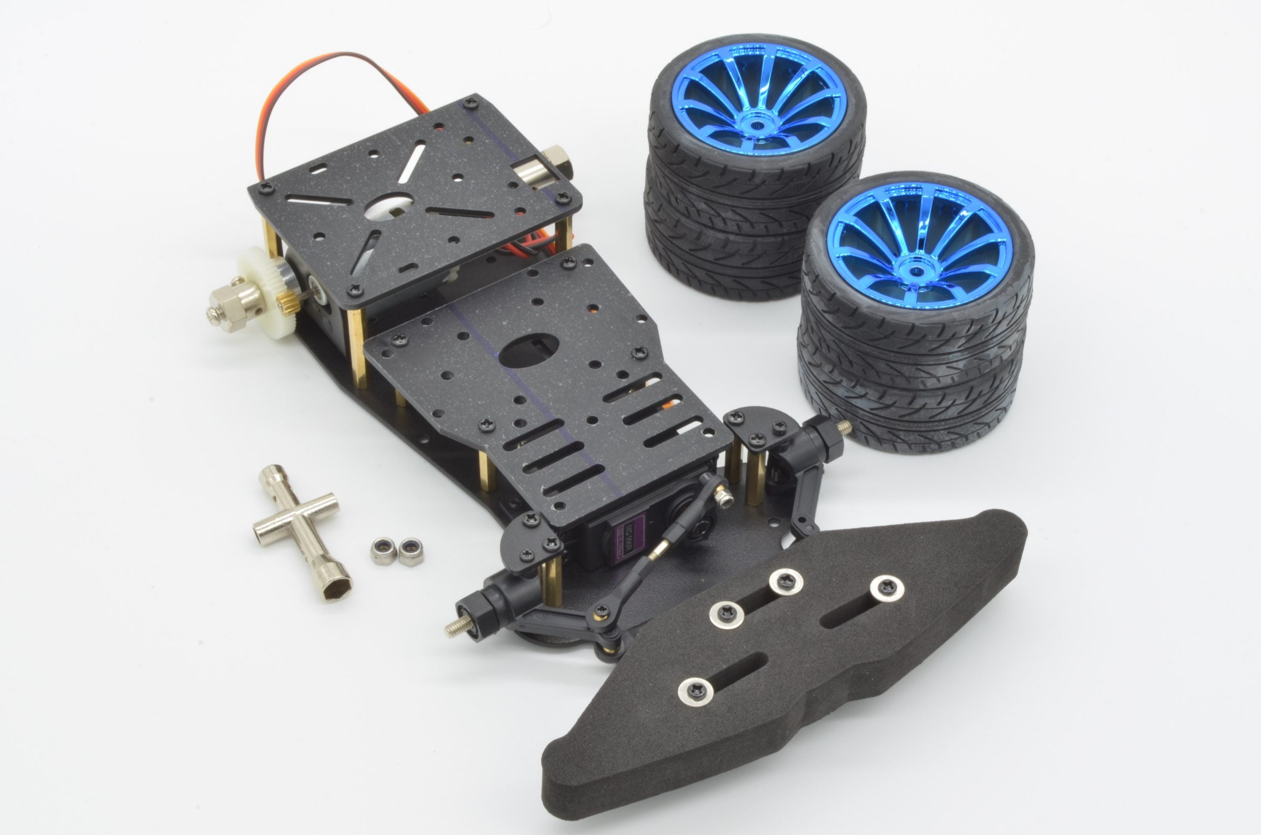
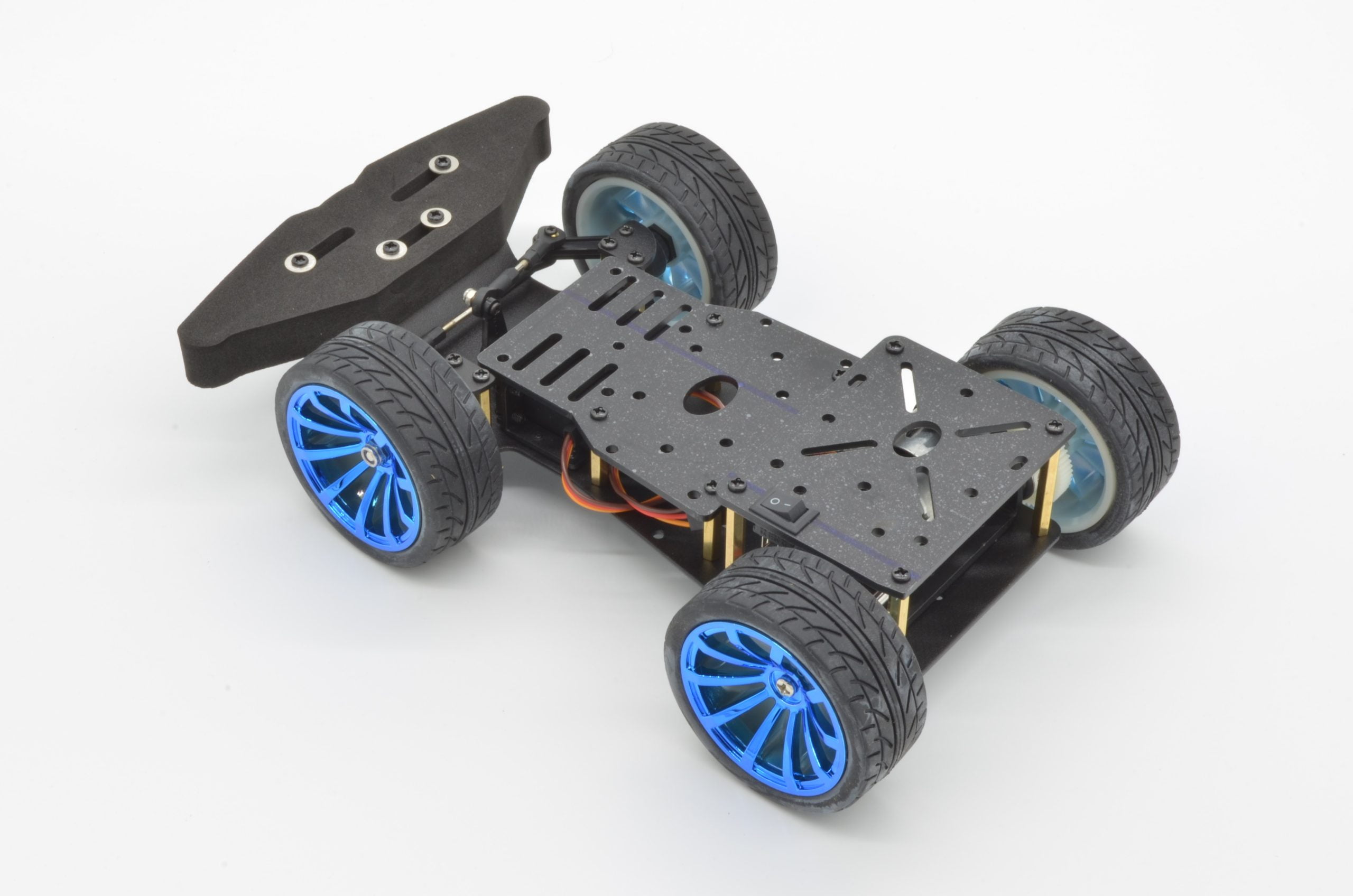
Step 13 - Installing The Wheels
Last but not least, let’s get those beautiful wheels installed! The fronts and rears used different hardware to attach to their axles. For the front wheels we will need 2 x M3 nuts and the included nut driver tool. For the rear, we will simply remove the screws already in the hubs, and install the wheels with the screws.
Your end result should be a chassis that looks like this! Of course, this is just the first step of building a self navigating robot. We will have tutorial looking at the electronics side, and choosing the right parts coming soon!