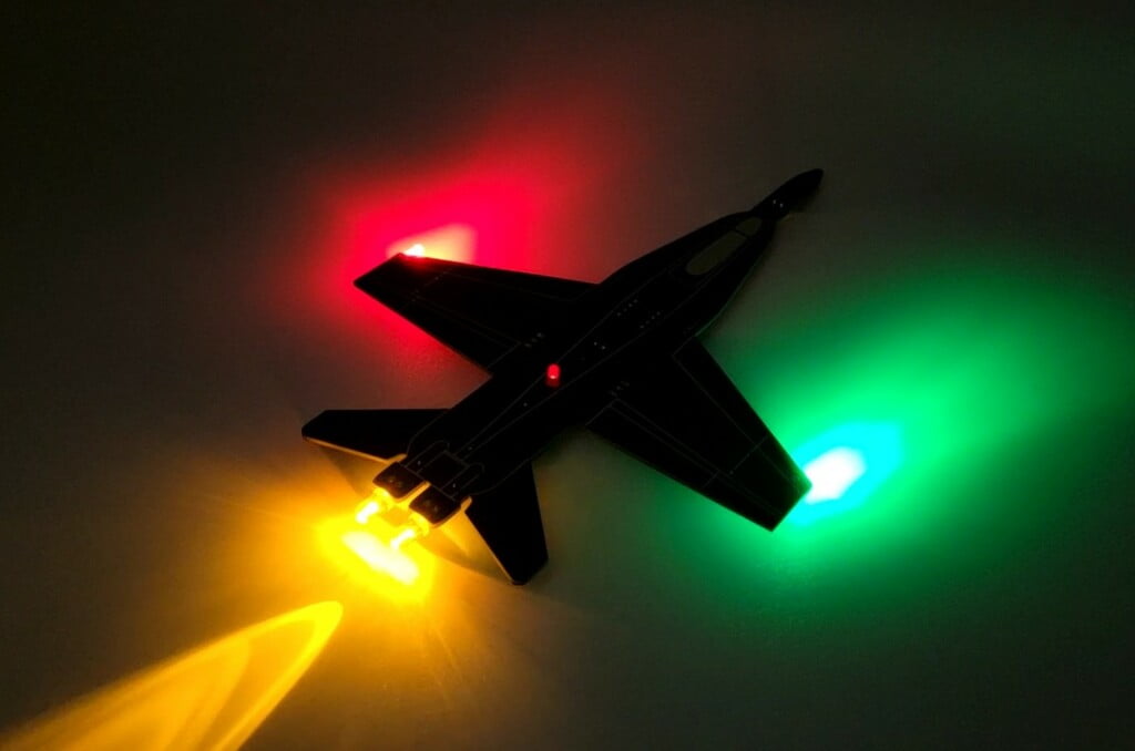
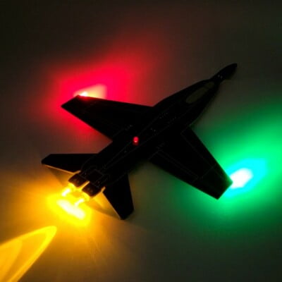
Soldering is often intimating, but it is an essential skill when working with electronics and the reality is it really isn’t that difficult when you have the right tools and a few pointers! The solder jet is designed to be a fun and easy way to learn to solder or brush up on your skills. The jet uses a variety of common components including transistors, resistors, a capacitor, a DIP switch, battery holder, and LEDs. Soldering these to the included circuit board results in an ultra-cool supersonic jet PCB with functional navigation lights, afterburners, anti-Collison strobe light, and even a landing light!
A Few Considerations:
Before we jump into soldering this board together there are a few points to consider.
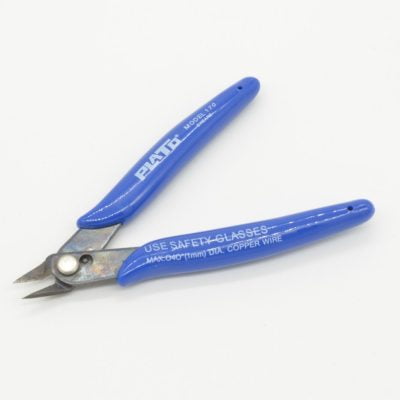
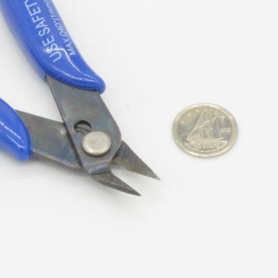
• Soldering irons and solder are extremely hot and will burn you on contact. Be very careful when handling the Soldering Iron and any components that have been freshly soldered. • When trimming the leads on components flush diagonal cutters can send sharp metal parts flying all over the room. Eye protection is recommended!
The Parts Needed:
This tutorial will require a few different things:
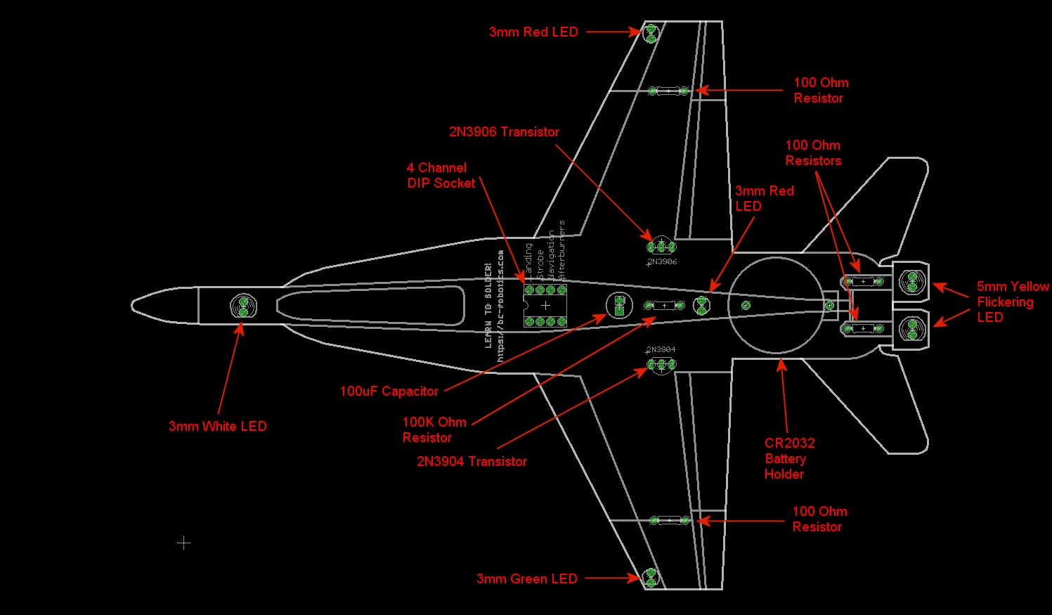
This handy little diagram shows how we will be connecting everything. This shows a “bottom” view of the board (the sided with “Learn to Solder” stenciled on it. Don’t worry if it looks a little overwhelming, we will be going through this step by step!
Step 1 - Resistors (Part 1)
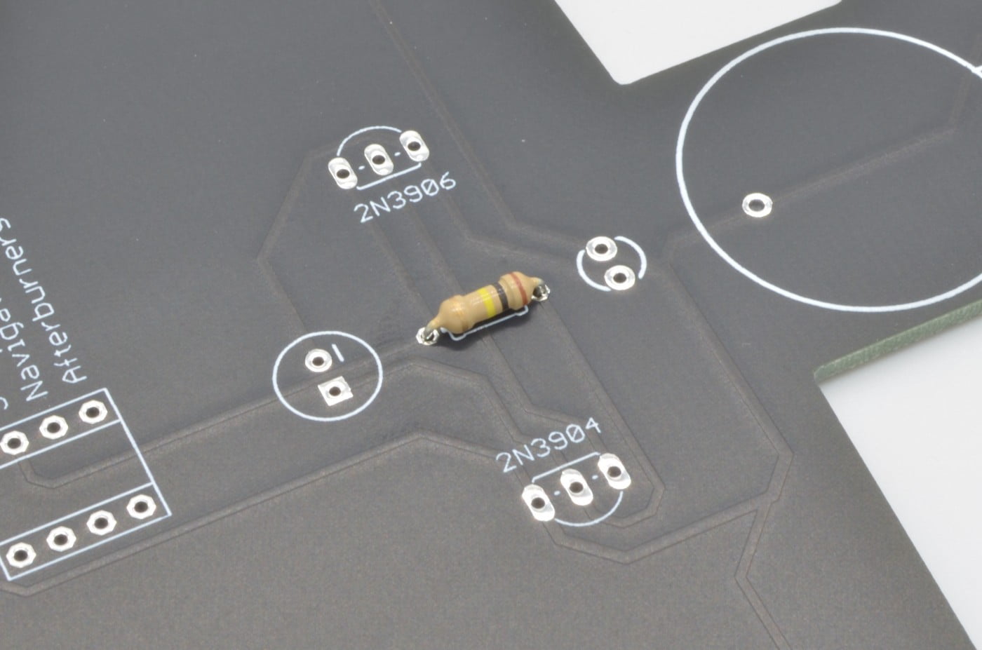
Generally when assembling any circuit board it is best to start with the shortest items first. In our case, this will be the resistors. There are two different resistor values used in this project; we will start with the odd one out, the 100K Resistor to get it out of the way.
Identifying the correct resistor can be a little tricky if you have never worked with them before. The colored stripes denote what the value of the resistor is – in this case we are looking for Brown | Black | Yellow | Gold. There is only one in this kit so it shouldn’t be too hard to find.
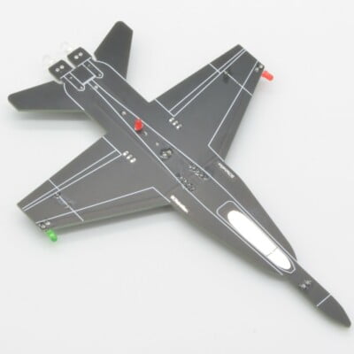
We are going to be installing all of these components on the bottom of the board/ The bottom has all of the outlines of the components and is the side without the shiny cockpit canopy.
Resistors do not have a positive or negative side and can be inserted either way. On each side of the resistor, bend the lead/leg 90 degrees tight to the end of the body of the resistor. Next, push it into the two resistor holes in the center of the plane (shown in the above diagram). If the resistor seems to sit crooked or the legs do not seem to want to go the entire way through the hole, pliers can be used to pull each leg through.
7.1%
Step 2 - Soldering The First Component
If you have never soldered before we highly recommend reading this Awesome Comic that illustrates all the basics of soldering before moving on!
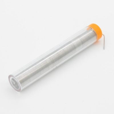
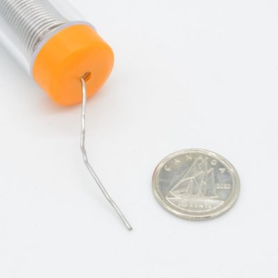
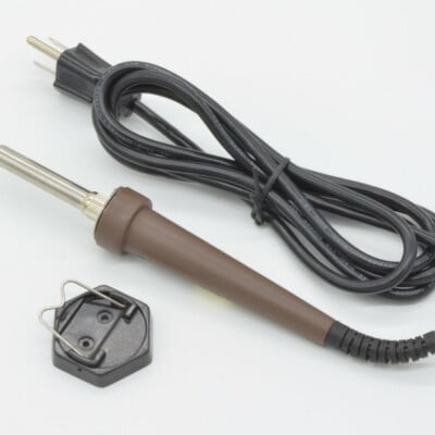
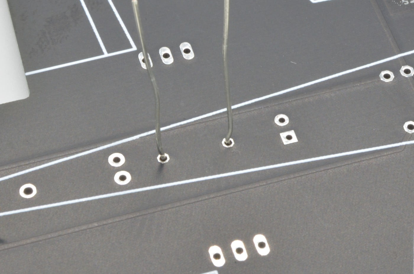
We are going to start by turning on the soldering iron, once it is up to temperature we can begin. Lay the board on its back so the resistor is on the table and rest the tip of the iron on the pad and the leg of the resistor. After a couple seconds (this will depend on the soldering iron you are using) push the solder into the pad until a small cone of solder has formed around the leg of the resistor and the pad. The iron can now be pulled away – let the solder joint cool before moving on to the next. Follow the same procedure with the second leg of the resistor.
14.2%
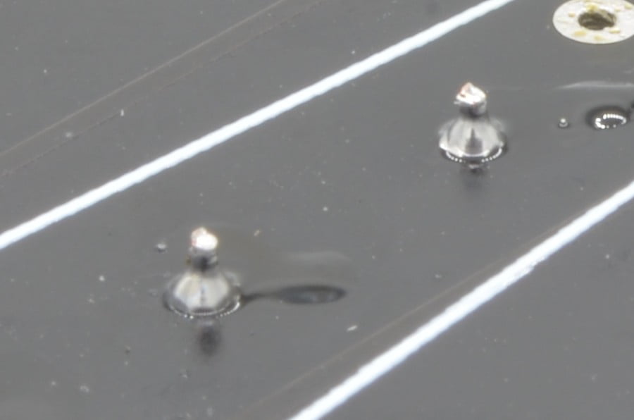
Step 3 – Trimming The Legs
Now trim each of the legs just above the solder joint to get rid of the excess. The end result should look like a small tent/pyramid of solder similar to ours!
We will keep following this same process of lining the component up, soldering it in, and trimming the legs for each component.
21.4%
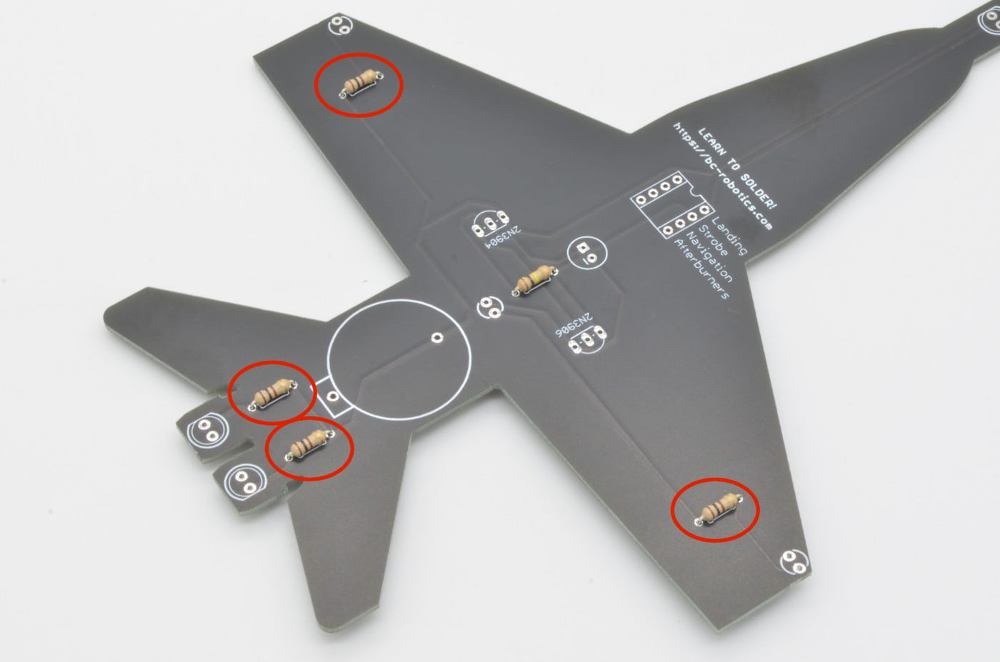
Step 4 – Resistors (Part 2)
Next, we will solder the 100 Ohm Resistors. There are four of these on the board. These can be identified by the Brown | Black | Brown | Gold banding.
Just as we did with the last resistor, install these in their respective places and solder in place. Once you are happy with the soldering, trim the leads.
28.5%
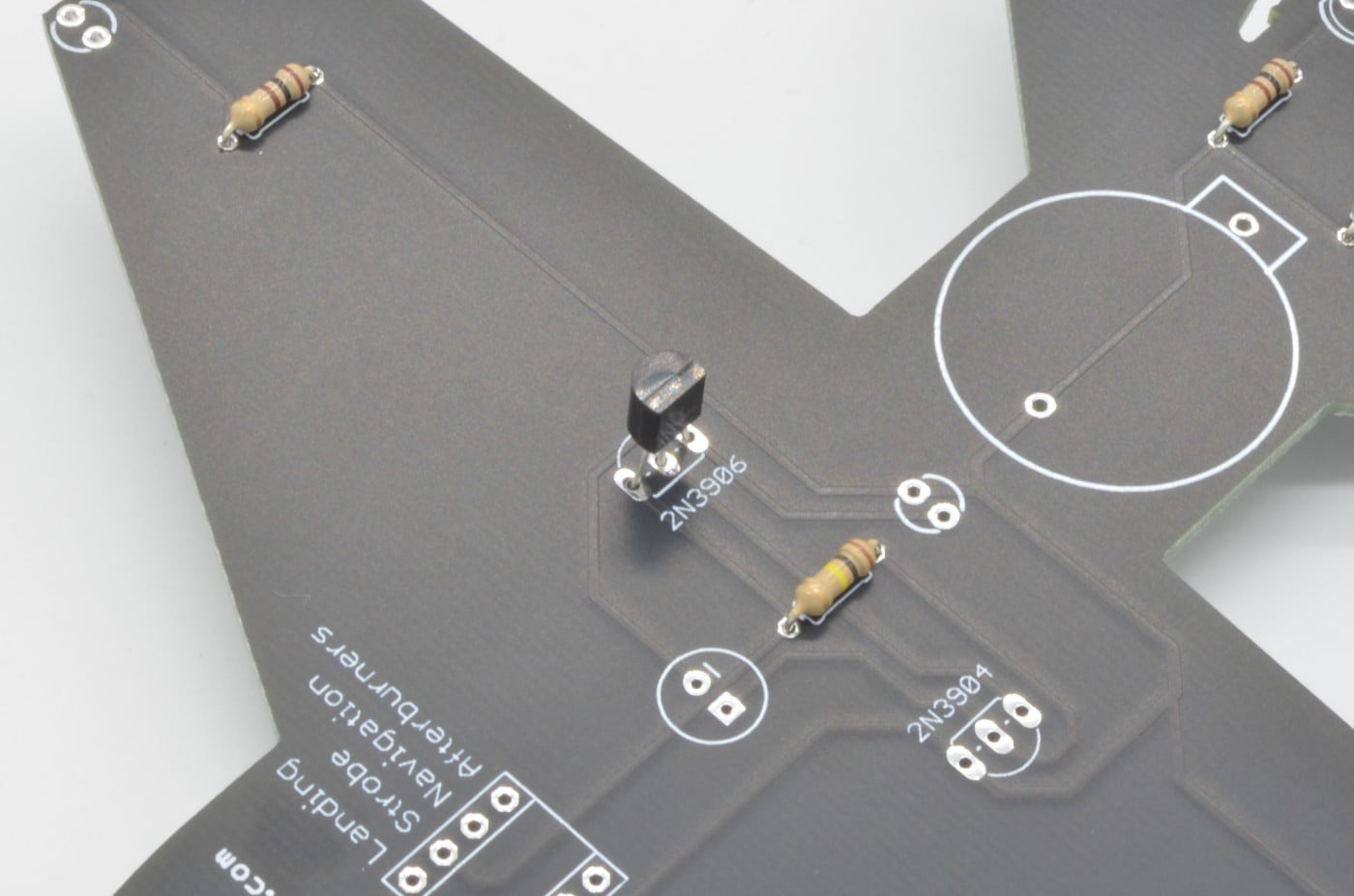
Step 5 - 2N3906 Transistor
As a part of the flashing anti-collision light circuit, we need to install two transistors. Both of these transistors are very similar and use and two identical footprints in the circuit board, so it is important to get the right one in the right spot!
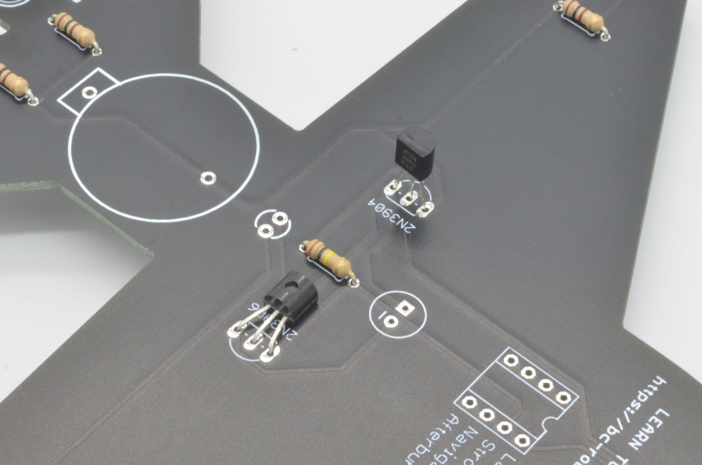
Finding the right one is not too difficult – the name of each one is stamped on the front. We are looking for the one labeled “3906”. The 2N3906 Transistor will go in the 3-pin footprint beside the text “2N3906” on the board. The flat side of the transistor should match up to the flat side on the footprint on the PCB.
The legs will need to be stretched outwards a little to allow them to fit the footprint, so feel free to carefully bend them. Once it is inserted flip the board over and solder the three legs. The legs can then be trimmed to length and , if desired, can be bent flush to the board as we have in our example.
35.7%
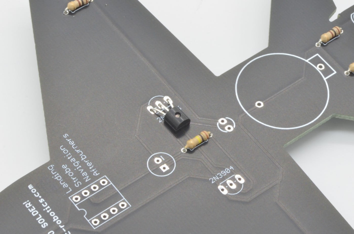
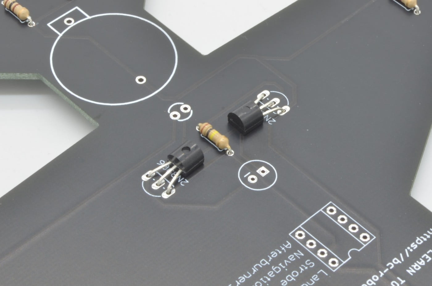
Step 6 - 2N3904 Transistor
Next, we will install the 2N3904 transistor. This transistor should be labeled 3904 on the front and fits in the second transistor footprint next to the label “2N3904” on the circuit board. This will be lined up the same way as the last one. Once it is lined up it can also be soldered in and trimmed to fit.
42.8%
Step 7 – Landing Light (LED)
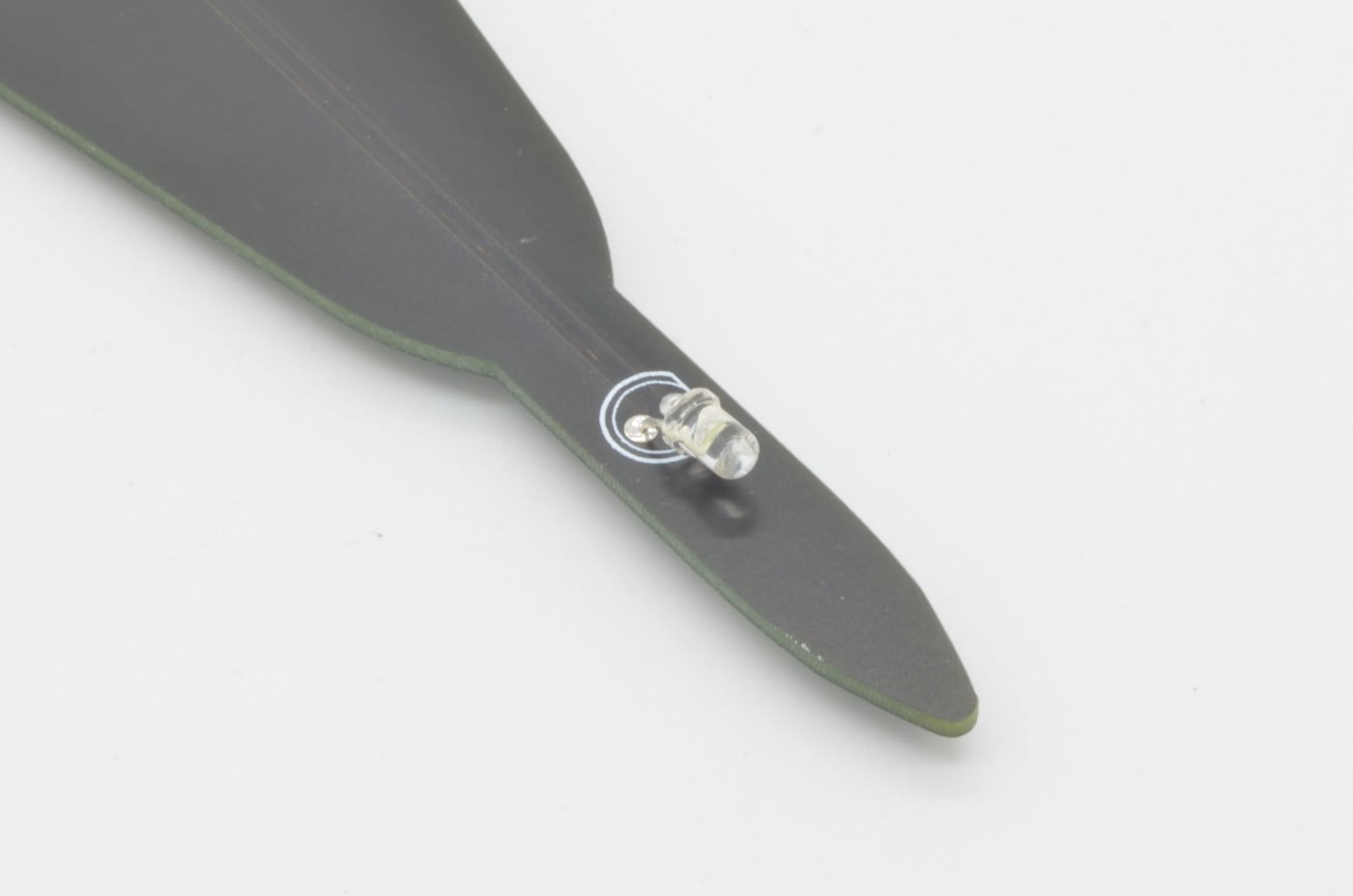
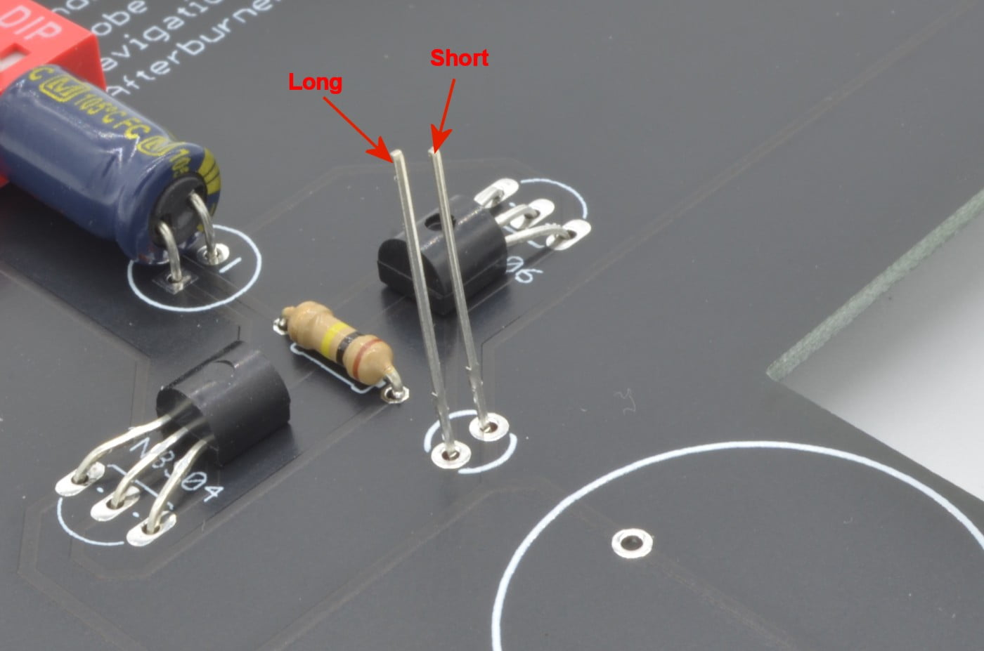
At the nose of the aircraft, we will install the White LED as a landing light. This is the smaller of the clear LEDs, so ensure you grab the right one! We need to make sure this part goes in the right way otherwise it will not light up. The LED has one side shaved down to give it a flat side. This should line up with the flat side on the PCB footprint, but if it is hard to tell, the flat side should always have the shorter of the two legs.
The LED will need to be bent flush to the board, and to do this we recommend bending the legs first. Fold them over 90 degrees so the LED is facing forward. Once you are happy with the position, solder it in place and cut the remaining leads of the back.
50%
Step 8 - Navigation Lights (LEDs)
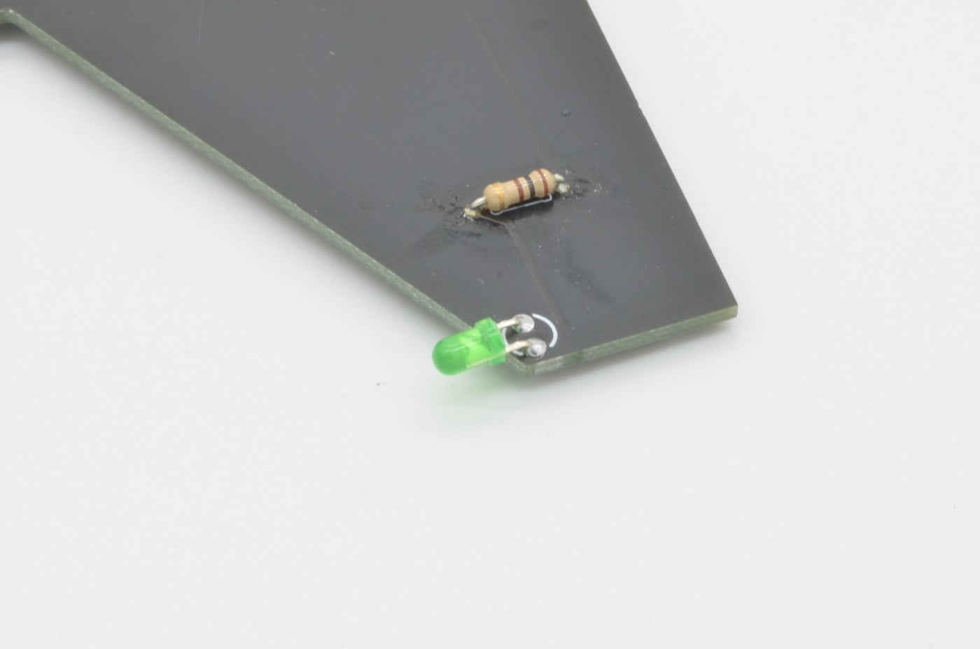
Next, we will move to the Navigation LEDs, found on the wingtips. These are the red and green 3mm LEDs. When looking at the bottom of the board, the Green LED should be on the left side, the Red on the Right.
It can be a little hard to see how these are aligned, but the shorter leg / flat side of the LED should be to the wingtip, with the longer leg closer to the center of the jet. These LEDs will both be folded flat as well, so be sure to align them before you solder them in place.
57.1%
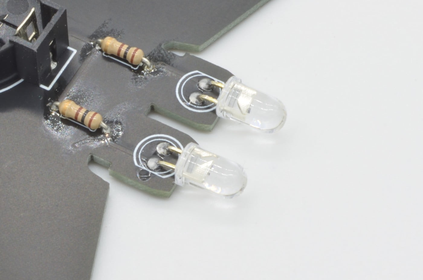
Step 9 – Afterburners (LEDs)
The afterburner LEDs are next – these are the larger 5mm Clear LEDs. These will be installed just like the last few, flat to the body. Align the flat side to match the footprint and fold these over so they hang off the back of the board as pictured. Once you are happy with the placement, solder them in and trim the excess.
64.2%
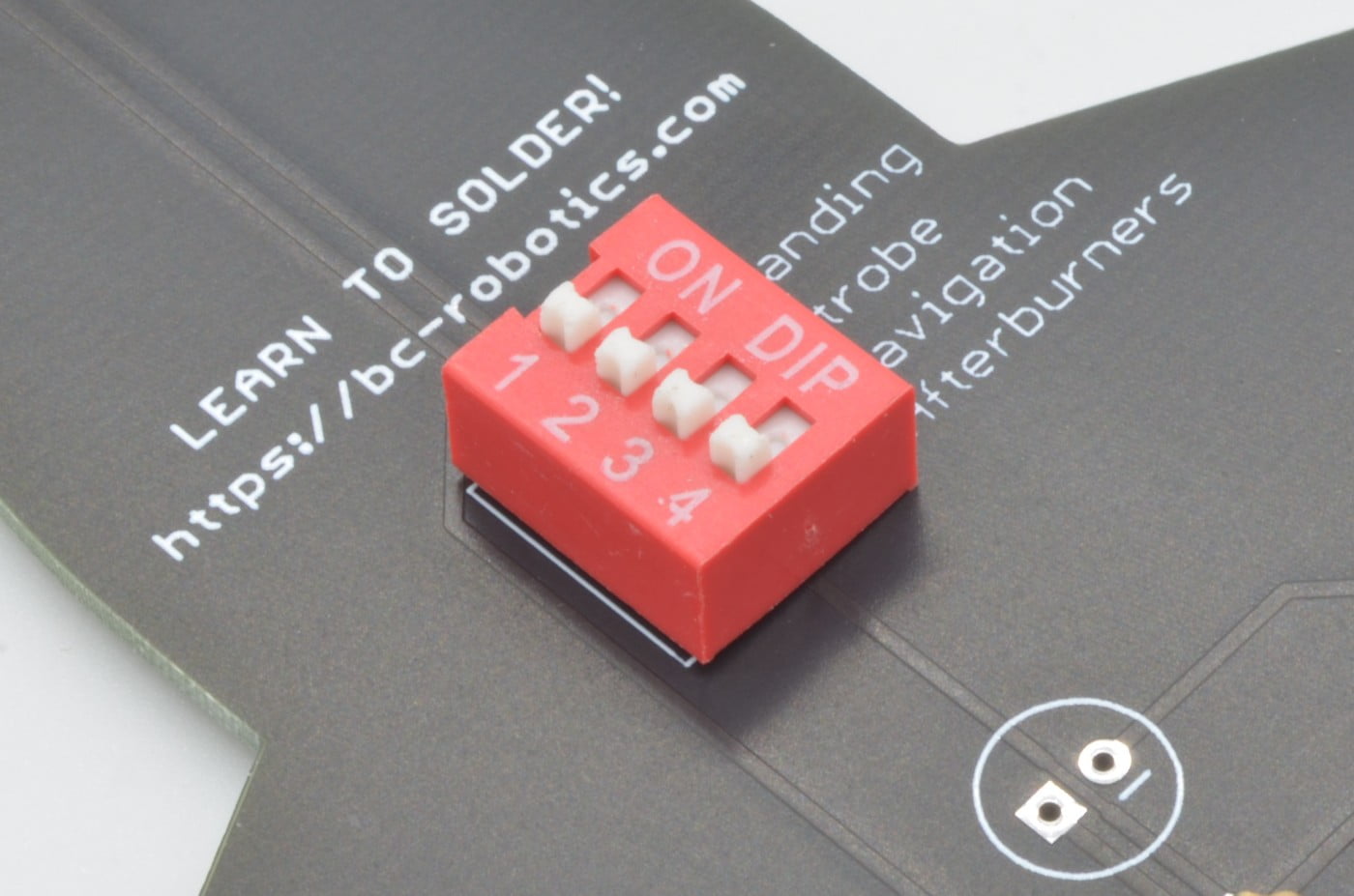
Step 10 - DIP Switch
We need to install the DIP switch next. This is a bank of 4 simple On/Off switches in an easy to handle package. We want the “ON” text to be on the same side as the description of what each switch does, so align the DIP as pictured.
Because the DIP has a lot of pins, we recommend soldering one pin first to ensure it is held in place and aligned correctly. Once you are satisfied with the positioning, solder the opposite corner, and check its placement again. If it is still sitting nice and flush to the board, finish soldering each of the pins.
71.4%
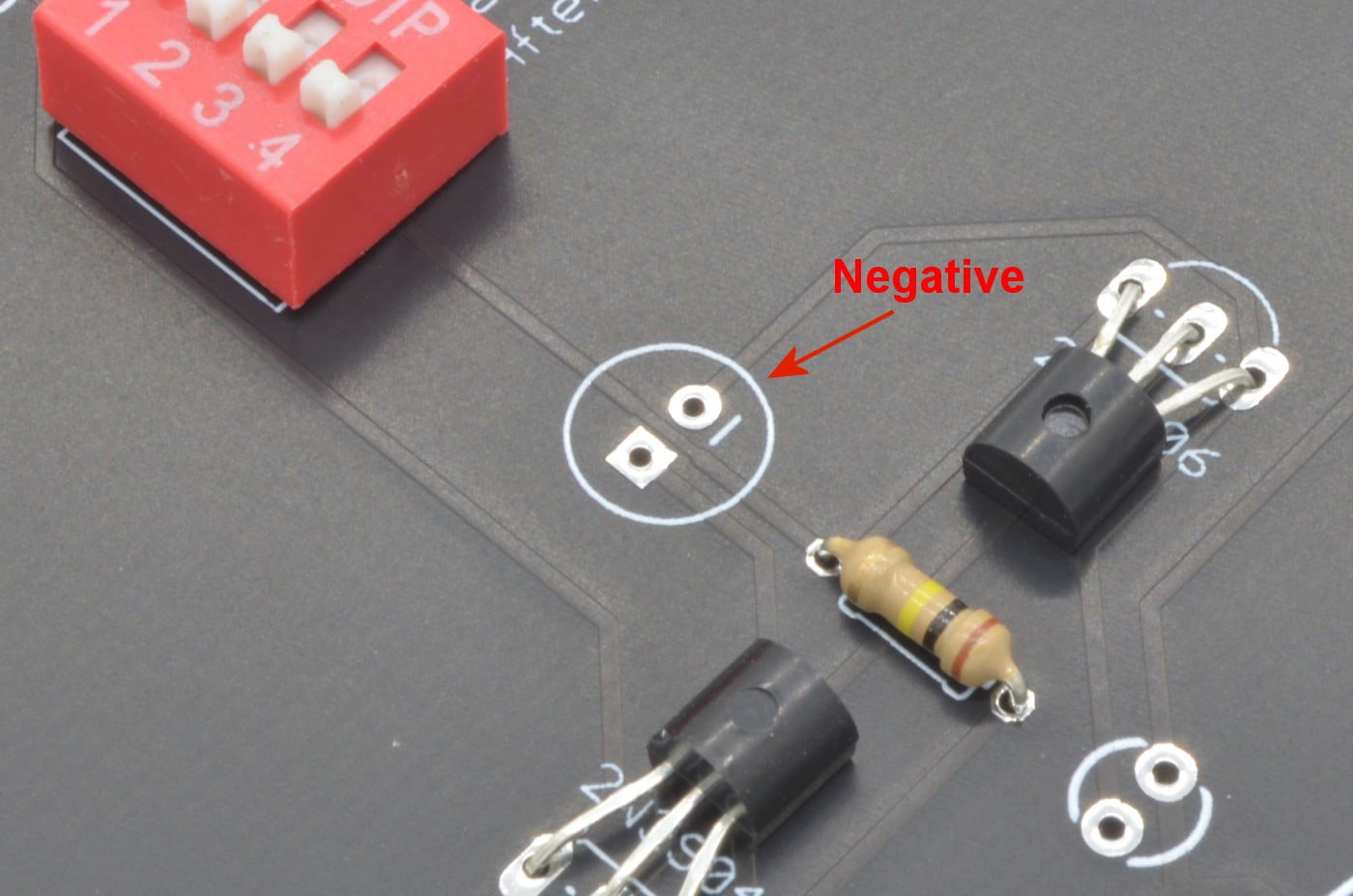
Step 11 – The Capacitor
The capacitor is just like the LED in the sense that it can only be inserted one way. It is placed just below the DIP switch we just soldered. One of the holes on the board is marked with a small “-” to denote which hole is negative. The Capacitor is also marked on one side with a stripe that indicates the negative side so aligning these to the correct orientation isn’t too difficult!
We are also going to bend this part to be flush with the board. Once you have the capacitor aligned, bend the pins flat against the base and slide the capacitor into the holes. It is a bit of a tight fit so the pins will have to be nearly flush with the base, as shown. Trim the pins once completed.
78.5%
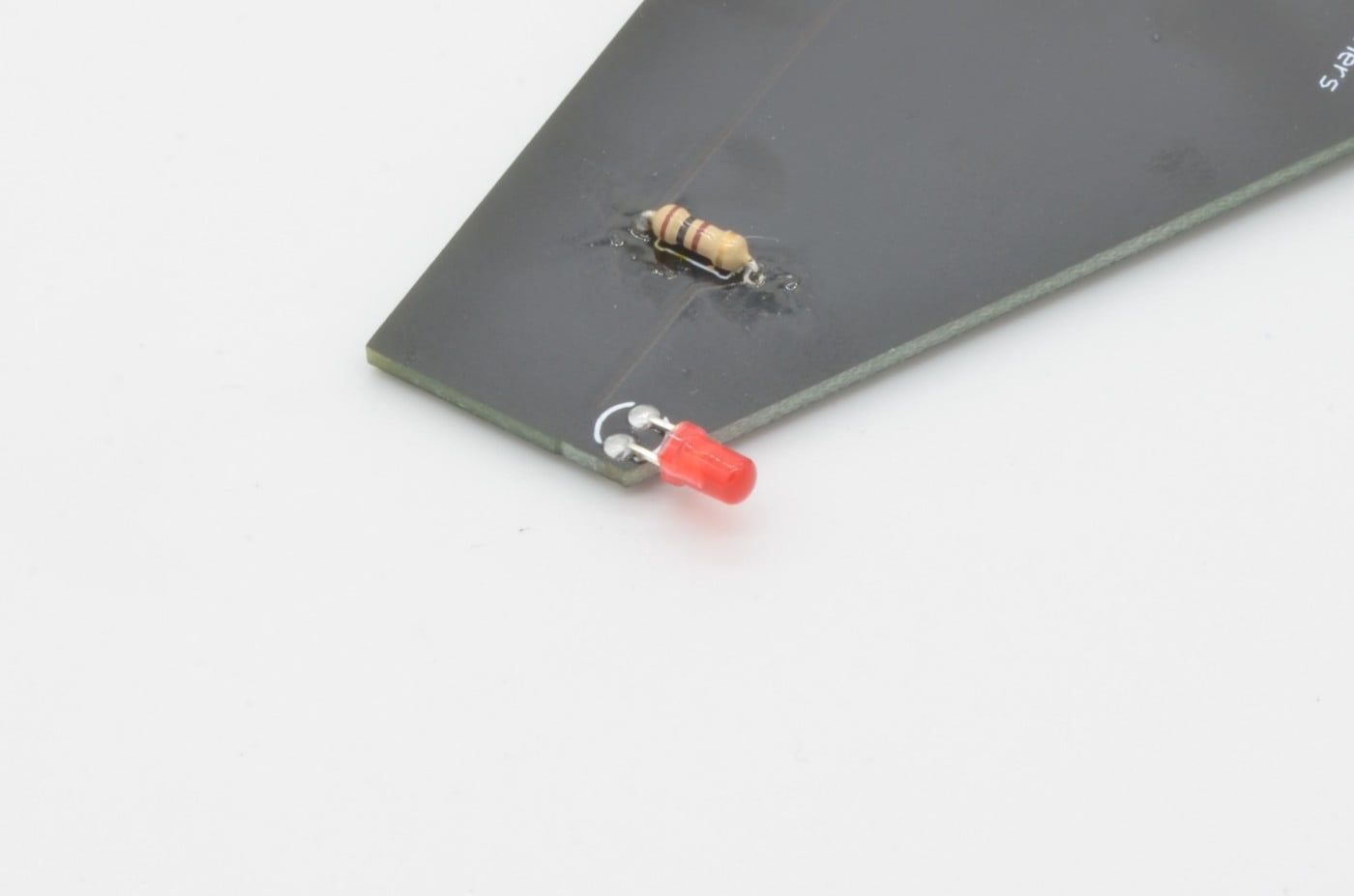
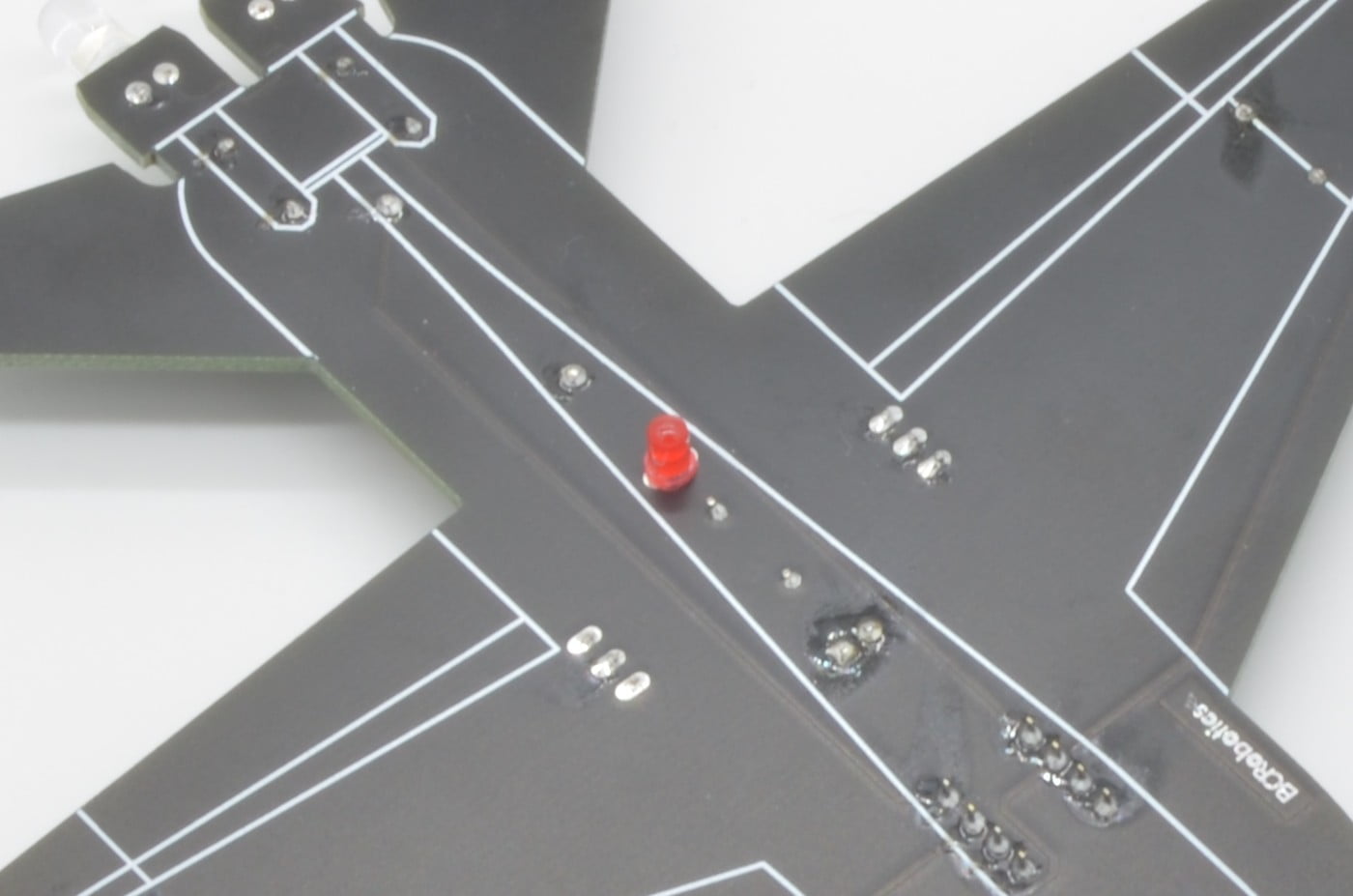
Step 12 - The Strobe (LED)
Next, we are going to install the last LED, another 3mm Red LED. This is the trickiest to install as it is going to be on the other side of the circuit board. The short leg of the LED should be closest to the other Red LED, while the long leg should be closest to the Green LED. The LED will be installed “normally” so it can be aligned and slid right down, flat to the board. Double check it is correctly installed, and solder in place. The leads can also be trimmed.
85.7%
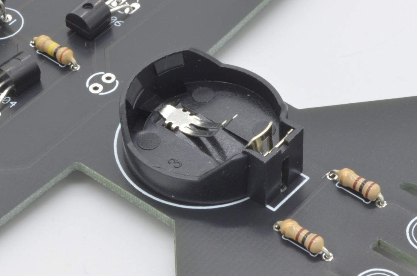
Step 13 – The Battery Holder
The battery holder is saved for last, as it is fairly large and easy to accidently hit with the iron. The holder can be aligned to the footprint and soldered in place.
With that, there should be no components left over. Double check all of your soldering joints and touch up if needed.
92.8%
Step 14 - Test It Out!
Time to test this out! Ensure all of the switches are in the off position (switches away from their labels on the board) and install the battery. While most CR20 series batteries will work, a good quality CR2032 is your best bet as they are fairly common and last longer than their smaller counterparts.
Try out each of the functions to bring the jet to life!
100%
One thought on “Solder Jet Assembly Guide”
Jack
Very nice little project. The end result looks pretty cool when I hang it up in my train room. O’scale.
I also get to practice desoldering as I unfortunately swapped nav lights and have the green light on port (left) side. Everyone should know portwine is Red 😆 🤣