BC Robotics
Browse categories
- New Additions
- Shop
- On Sale / Clearance
- Popular Categories
- ArduinoArduino is the most popular open source microcontroller platform on the market. These easy to program devices can read sensors, control relays, light up LEDs, and even talk to one another. Their ability to interact with the real world by way of sensors and other electronics makes them ideal for automation such as watering a plant when it is dry, reading the weather, or controlling lights when it gets dark – the possibilities are endless. We carry a variety of Arduino compatible microcontrollers from several manufacturers, each with their own specific strengths and purposes. To further specialize your microcontroller, we carry a large selection of daughter boards (shields) which can add powerful sensors, GPS, or even LCD screens to your project! Just getting started with microcontrollers? We carry a variety of Arduino starter kits to get you reading sensors and blinking lights as easily as quickly as possible!
- BBC micro:bitThe BBC micro:bit is a pocket-sized computer designed for beginners in electronics and coding. The micro:bit makes getting into these often daunting fields as easy as possible. Programming the micro:bit V2 can be done by computer or by their intuitive app available for Android and iOS devices. Code can be designed using a drag and drop interface in the Blocks editor, Javascript, or Python.
- ESP8266 & ESP32The ESP8266 and ESP32 microcontrollers from Espressif are powerful, inexpensive, and feature integrated WiFi connectivity. These are ideal for IoT applications. We offer a variety of different ESP8266 and ESP32 modules for different skill levels.
- FeatherFeather is a flexible and powerful family of microcontroller main-boards (Feathers) and daughter-boards (Wings) designed with portability in mind. All Feathers have integrated battery connectors (and most have built in lipo chargers) The Feather form factor is not locked to a specific chipset or programming language. Feathers are available with a variety of chipsets and on-board features. Most Feathers and FeatherWings have example code and libraries written in Arduino C/C++ and CircuitPython.
- Makey MakeyThe Makey Makey kit is a electronics kit designed for beginners. It explores the concepts of creating circuits through everyday items. When plugged into a computer you can use the Makey Makey to make anything into a keyboard or mouse. No programming required! Projects like a Banana Drum Set, Cat Detector, Musical Stairs, and countless others are easier than you think! We carry the Makey Makey Classic Kit – a starter kit for the Makey Makey – along with extra alligator clips, copper conductive tape, and replacement cables.
- Raspberry PiThe Raspberry Pi was first introduced in early 2012 as a simple, low cost, computer fit onto a circuit board roughly the size of a credit card. The idea was to use this low cost computer to promote teaching of computer science in schools but it has grown to be so much more! Since its release, well over 30 million of these little computers have been sold. We have carried the Raspberry Pi in Canada since it first became available and have watched as the Pi has morphed into a complete development platform with powerful single-board computers, cameras, touchscreens, and other accessories. Its multitude of inputs and outputs for electronics and computer peripherals and its impressive computing power mean it can be used to make just about anything you can imagine. The newest and most powerful version, the Raspberry Pi 4, is now available!
- Popular Brands
- AdafruitAdafruit was founded in 2005 by MIT engineer, Limor “Ladyada” Fried. Her goal was to create the best place online for learning electronics and making the best designed products for makers of all ages and skill levels. In the last 10 years, Adafruit has grown to over 100+ employees in the heart of NYC with a 50,000+ sq ft. factory.
- ArduinoArduino is an ever growing platform used by some of the most popular microcontrollers out there. For many of us, this is where it all started – the Arduino was (and still is today) a pioneer when it comes to making programming hardware easy and accessible. We have one of the largest selections of Arduino and Arduino accessories in Canada. These range from basic Arduino Uno, to Cellular and WiFi connected devices perfect for the Internet of Things, and all the accessories needed to get them running!
- Micro:bitMicro:bit Educational Foundation are the manufacturers of the popular BBC micro:bit; a pocket-sized computer designed for beginners in electronics and coding. The micro:bit makes getting into these often daunting fields as easy as possible. Programming the micro:bit V2 can be done by computer or by their intuitive app available for Android and iOS devices. Code can be designed using a drag and drop interface in the Blocks editor, Javascript, or Python.
- BC RoboticsIn addition to stocking 2000+ unique items, we also manufacture our own accessories right here at BC Robotics. In 2014 we began developing our own widgets and add-ons for Arduino, Raspberry Pi, and general prototyping. This has now grown to over 80 different SKUs. Our boards are assembled in-house with top quality components. Many feature detailed tutorials or project guides to get you up and running as quickly as possible!
- Raspberry Pi
- SparkFunSince 2003, SparkFun has been helping turn ideas into reality – whether you’re creating a smart weather station, exploring the frontier of machine learning, building a robot for school or prototyping your first (or tenth) product. No matter your vision or skill level, our open source components, resources and online tutorials are designed to broaden access to innovative technology and make the road to a finished project shorter. We’re here to help you start something.
- Frequently Asked Questions
- My Account
- Wishlist
- Cart
Product Guide – 2 Channel Arduino Relay Shield
Product Guide
Table Of Contents
Shop Now
Similar Products
Overview
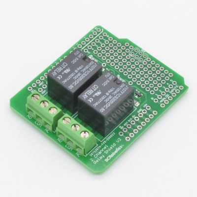
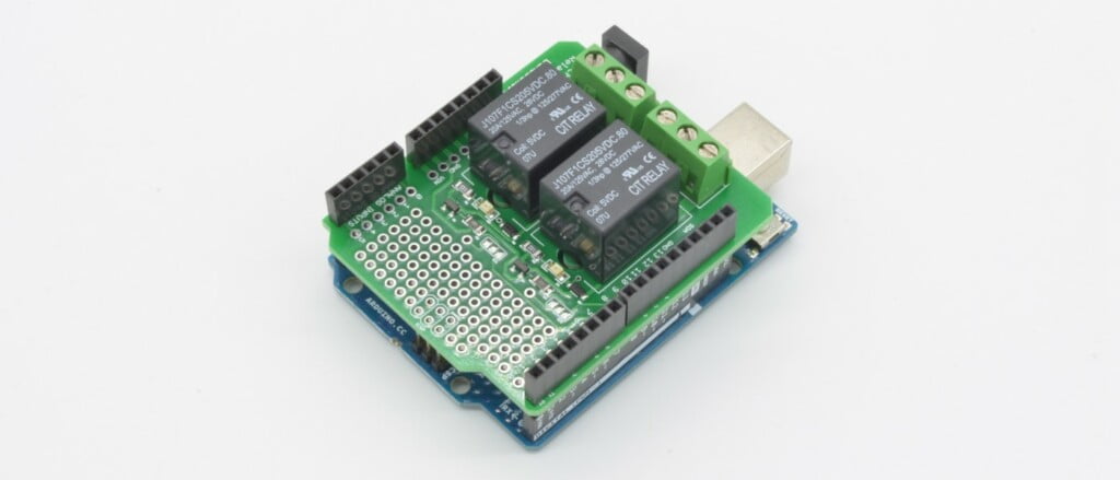
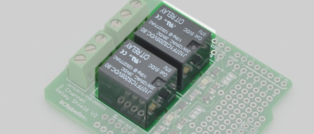
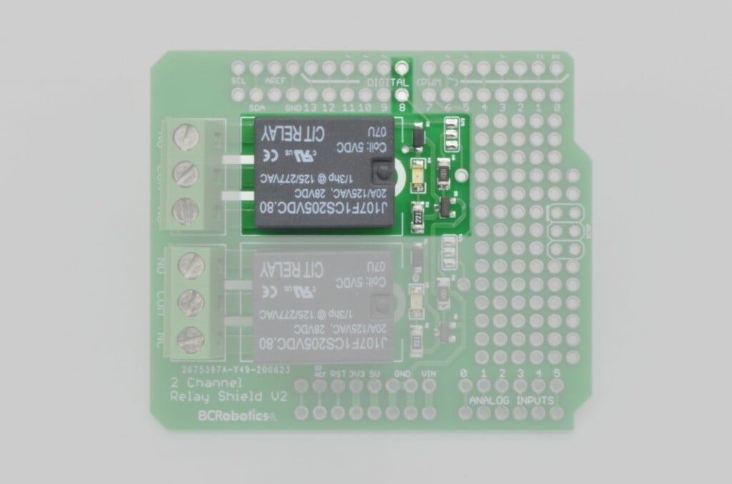
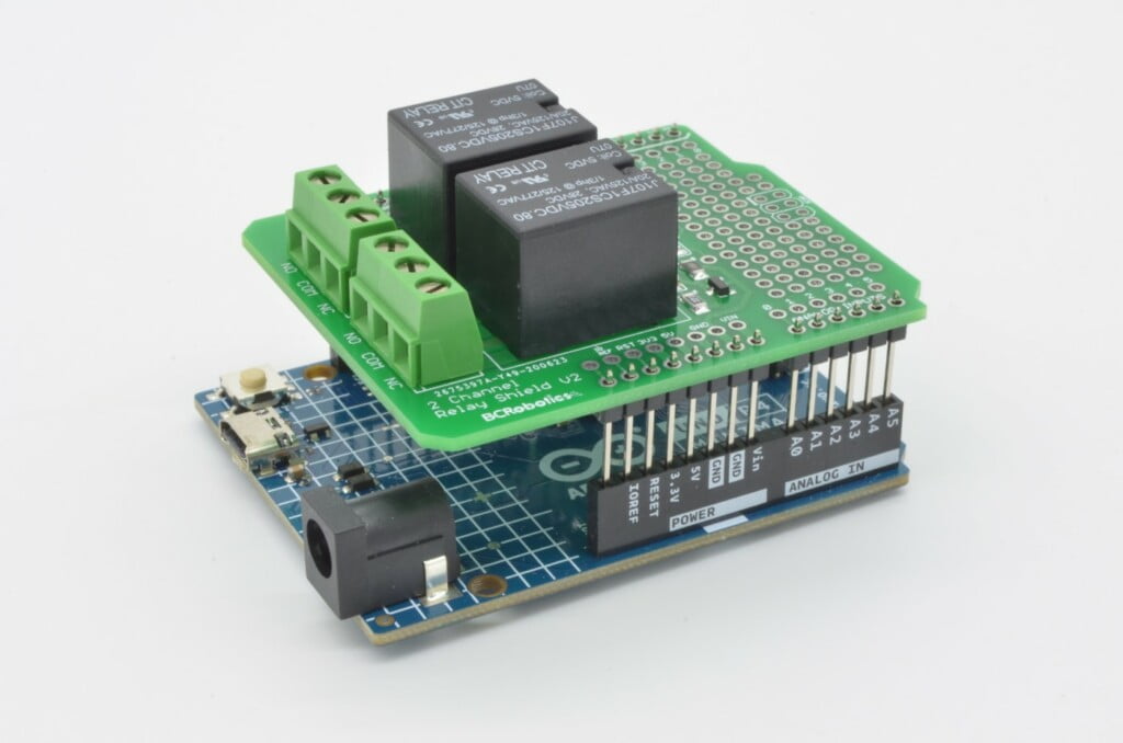
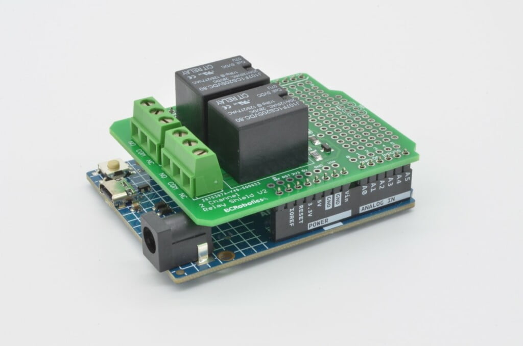
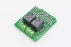
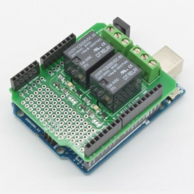
The Arduino Relay Shield is an add-on board for any Arduino Uno microcontroller. This board is designed to make connecting a relay to your Arduino as easy as possible. The board features two 10A / 250VAC relays and all the support circuitry required to control them. The Relay Shield is manufactured in Canada with North American sourced relays and electronic components. With headers installed, the Arduino Relay Shield and Arduino form a compact and reliable control package.
The board is constructed around two sealed relays. Each of these relays is rated to a minimum of 10A on each contact at 16VDC or 250VAC. As relays cannot be directly controlled by an Arduino, each relay has transistor-based control circuit, complete with flyback diode and an indicator LED. The indicator LED is illuminated when the relay is energized. Each relay is used in a dry contact configuration, and both relay contact sets are completely independent from the other.
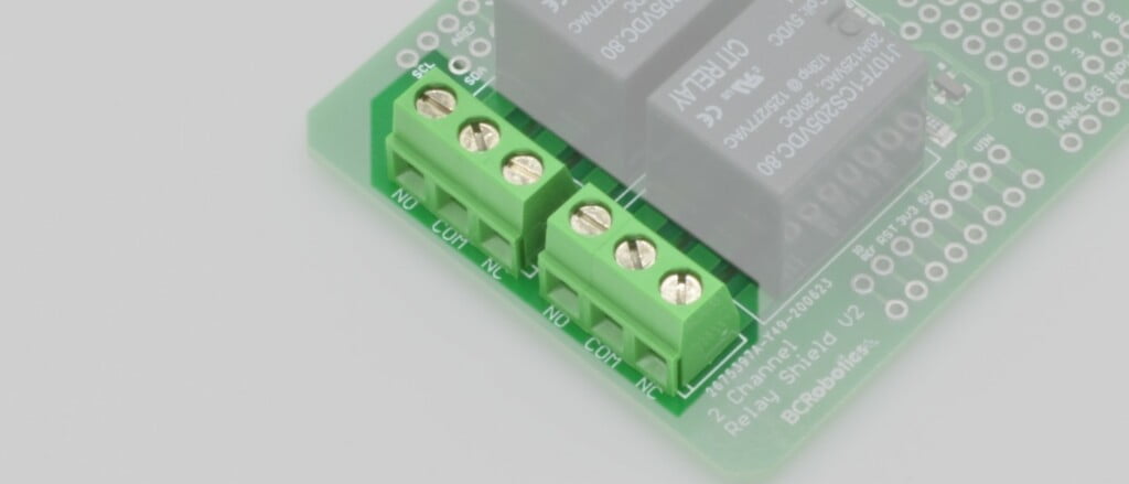
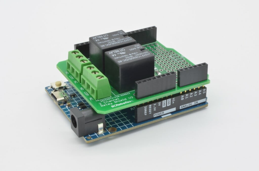
Large, high quality screw terminals are used to connect all the high voltage / high current contacts on each relay. Each terminal is rated at 300V / 13.5A per contact and will accept wires from 16AWG down to 30AWG. All connections to the Arduino are made via the stacking headers. On this board we use the Uno R3 Version of the Arduino Stacking Header configuration. Standard breakaway headers or stacking headers can be installed on this board depending on the application.
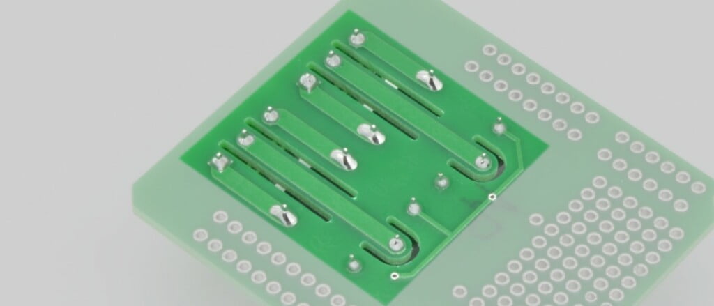
Because devices are not always operating in a pristine environment, air gap isolation is routed into the board. This is done to reduce any leakage current between the higher voltage / current portion of the board and the low voltage Arduino. As time goes on, dirt and moisture may accumulate on a PCB, this can allow a small amount of current to flow in undesirable ways. Increasing the creepage distance with these air gaps reduces this.
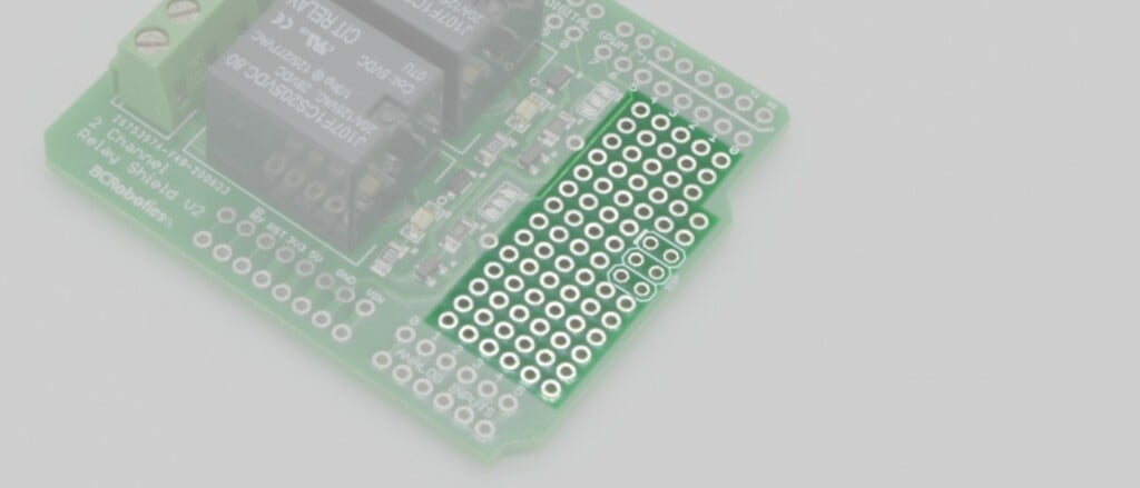
A large prototyping area is also made available in the extra space on the circuit board. The roughly 5 x 14 grouping of plated through-holes are not interconnected and allow for the permanent installation of additional connectors or components to complete your device. These feature a standard perfboard / breadboard pitch of 2.54mm ( 0.100” ).
Product Details
-
Part Number:ARD-036
-
Manufacturer:BC Robotics Inc.
-
Made In:Canada
-
Board Power:5VDC
-
Logic Voltage:5VDC
-
Soldering Skill:BeginnerPrototyping Skill:IntermediatePrograming Skill:Beginner
Compatibility
Compatible with all Arduino and Arduino compatible boards with 5V available using the Arduino R3 pin standard.
Example Uses
The board was intended be used for basic automation scenarios such as switching something on or off at a specific time or based on a sensor input. Some examples:
- Supply power to a heating pad when the temperature drops below a certain value.
- Supply power to a LED flood light when motion is detected.
- Supply power to a small pump when water reaches a certain height.
- Run a fan for 5 minutes every hour
Pinouts & Connectors
All Arduino pins are brought up through the header. While this board does not make use of most of them, we have doubled them up next to the headers to give easy access to all pins just incase you need to configure the relays to use alternate control pins, or they are needed for extra circuitry in the prototyping area.
Power Pins
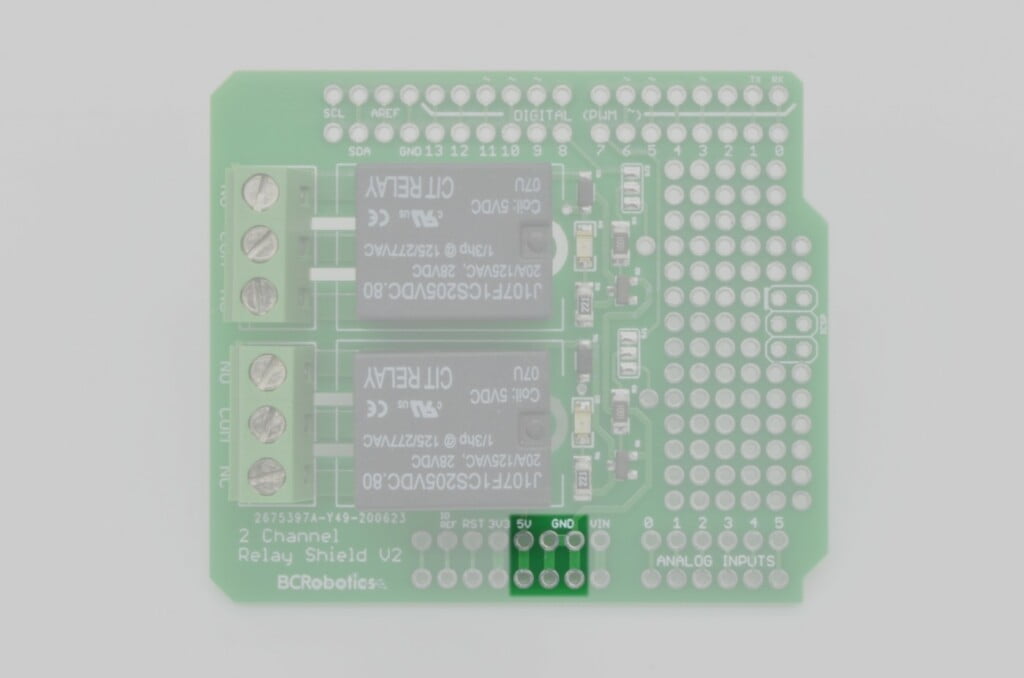
In the Arduino R3 configuration the 8 pin “Power” header provides access to all power and the reset pin of the Arduino. The Arduino Relay shield brings all 8 pins onboard and provides an additional access point for each pin. The shield uses the 5V pin and GND pins to power the relays and indicator LEDs.
Analog Header
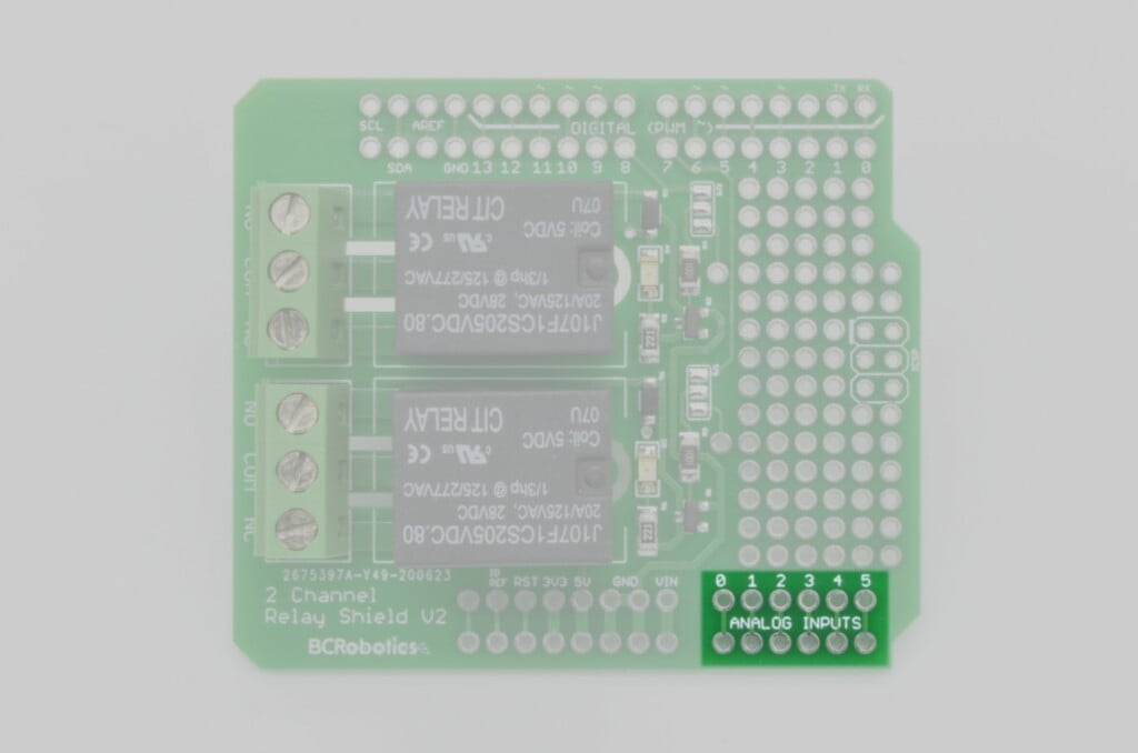
The 6 pin Analog Input Header is unused by the shield, but we do provide an additional access point to each pin on the shield.
ICSP Header
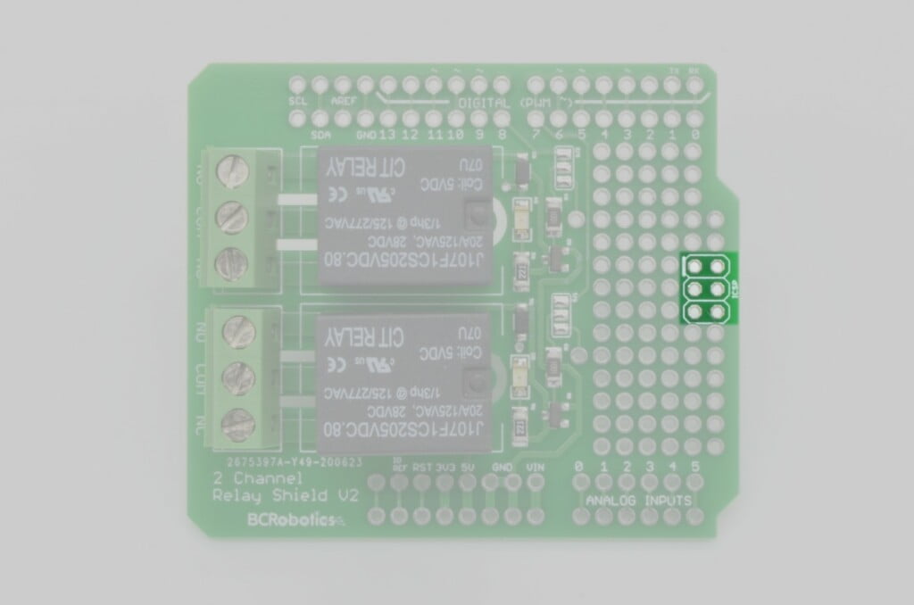
The 2×3 pin ICSP header is unused by the shield, but the pins are located in the correct location and can be used as a pass through if needed. If not needed, these pins are not connected on this board and can be included as part of the prototyping area.
Relay Control Circuits
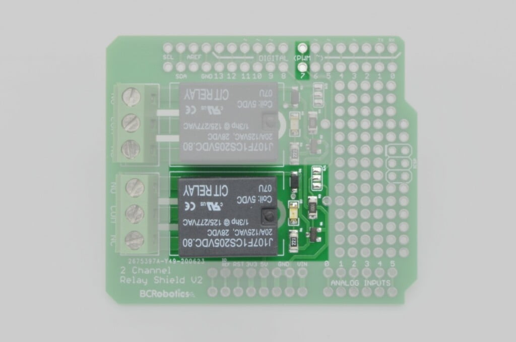
The shield uses digital pin #7 as control for Relay #1, this is contained within the 8 pin Digital Header. All other pins are unused, but access is provided to them by way of an additional access point.
The second relay is controlled by digital pin #8 within the 10 pin Digital Header. All other pins are unused in this header, but access is provided to them by way of an additional access point.
Screw Terminals
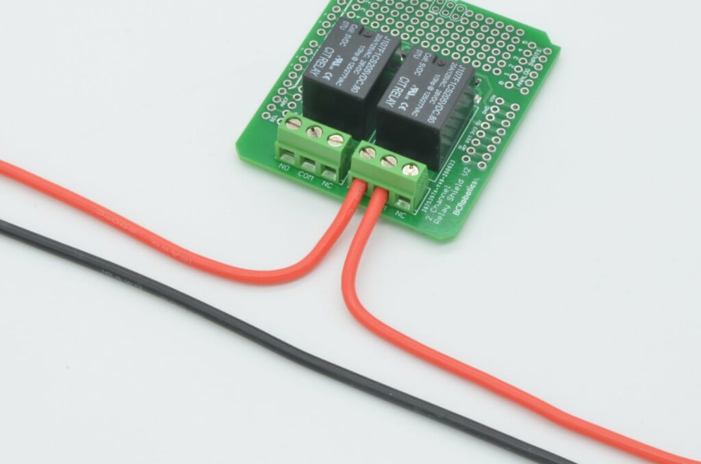
Each relay features a large 3-pin screw terminal for connection to each of the high voltage / high current contacts of the Relay. The screw terminal is rated at 300V and 13.5A per contact.
Both relays are used in a dry contact configuration and the contact sets are completely independent from the other. Each screw terminal provides access to the adjacent relay’s COM (Common) pin, NO (Normally Open) pin, and NC (Normally Closed) pin. The COM pin connects to the common pin on the relay, while the NO and NC pins connect to the NO and NC pins on the Relay.
Using Alternate Arduino Pins
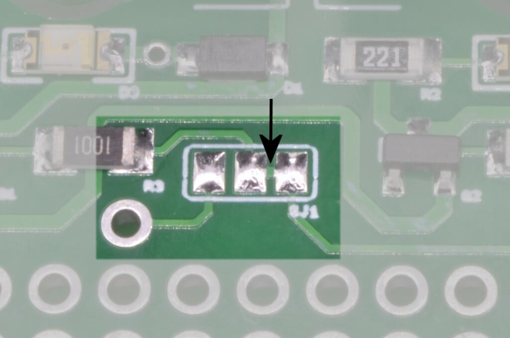
If there is a conflict between the pin requirements of the 2 Channel Arduino Relay Shield and another board, we have set the relay shield up to be able to use alternate pins. Each relay has a solder jumper that allows for the control line to be diverted to a through hole pin rather than the Arduino pin. From this through hole pin, wire can be routed to an alternate Arduino pin on the board.
To use these solder jumpers, a trace will need to be cut between the two pads. A hobby knife or even a small flat blade screwdriver with a sharp corner will easily break the connection. Cut / scribe at the arrow in the below photo.
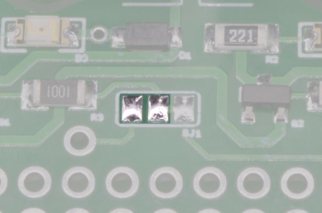
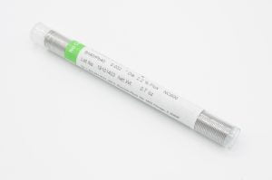
If you have a multimeter handy, check there is no continuity between the two pads. Now that the connection is broken, use a soldering iron and a blob of solder to bridge the middle pad and the opposite pad instead.
If this modification ever needs to be reverted back to the “Normal” pin, just remove the solder blob, and create a new one that replaces the trace that was cut before.
Arduino Pins Used
5V
GND
D7
D8
Based on Arduino R3 Standard. Clone boards may vary.
Alternate Pin Options
YES
Provisions for modifying control pins available. Soldering required.
External Connections
SCREW TERMINAL
Assembly
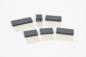
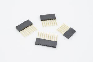
The only assembly required with the 2 Channel Arduino Relay Shield is the addition of breakaway headers or stacking headers. Both options can be used, and it will be up to your application whether stacking headers are needed or not.
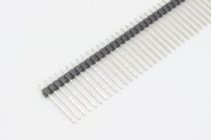
For the simple stacking of this board on top of an Arduino Uno R3 we recommend our Breakaway Male Header – Long. These tall headers give a little extra clearance over the larger USB input on the Arduino.
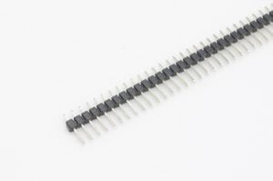
For boards such as the Arduino Uno R4, Arduino Leonardo, SparkFun Redboard, or Adafruit Metro, where clearance is not an issue, Breakaway Male Header – Standard can be used to create a more compact assembly.
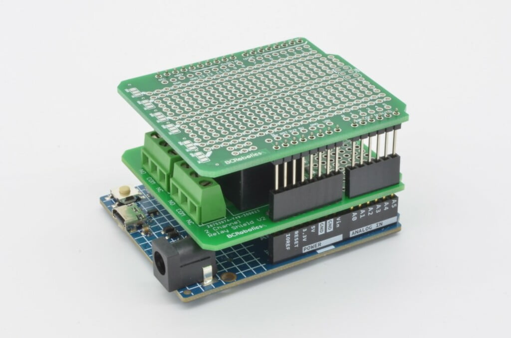
If you wish to stack on top of this board, using our Arduino Stacking Headers will work. It should be noted that with stacking headers, the height required to clear the relays is significant. Our Breakaway Male Header – Long will be required for the board above it.
Recommended Connectors
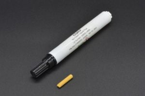
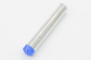
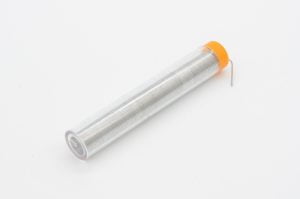
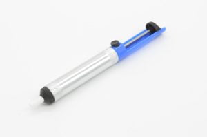
Soldering Accessories
Using The Board
The 2 Channel Arduino Relay Shield uses non-latching conventional relays to switch high voltage / high current devices. These relays are well suited for many applications and effectively act as a SPDT (Single Pole, Dual Throw) switch that is controlled by an Arduino.
The operational logic of this board is very simple; when Digital Pin 7 or 8 are set to the “HIGH” state with your Arduino, the respective relay coil is energized, triggering the relays to change contact positions. As long as the digital pin remains “HIGH”, the coil will remain energized in the “ON” state. If the Arduino pin is set “LOW” or power is lost, the relay will immediately return to its original “OFF” contact position.
The mechanical relays used on this board are not designed for high speed switching. While they can typically engage within 10ms and release within 5ms, the switching frequency should be kept to a minimum. For high speed switching, we suggest looking into Solid State Relays or Power MOSFETS.
Normal use would see a power source run through the COM pin of the relay. The output would be then run to the device from the NO (Normally Open) or NC (Normally Closed) contact. Which contact would be determined how you want the system to react.
- If this is something that is supposed to be off the majority of the time, but turned on intermittently, you would generally use the NO contact.
- If this is something that you want to interrupt power to from time to time, but is on the majority of the time, generally you would use the NC contact.
Safety
Please be aware: Due to the relays and terminal blocks used on this board being through hole components, any high voltages used will be exposed on the bottom of the board where these components are soldered to the circuit board. As with all high voltage applications, if you are not familiar with best practices and proficient in working with high voltage devices, we recommend consulting a professional.
Source power should be appropriately protected with a fuse or circuit breaker designed for your application. High current or high voltage devices need appropriately rated wire, fusing, and protection.
Code Examples
Pump Control
Very basic Arduino code to supply power to a small pump when water reaches a certain height. Pump connected through Relay #1
					const int waterSensorPin = 3;   // Water level sensor connected to digital pin 3
const int relayPin = 7;         // Digital pin 7 for Relay #1

void setup() {
  pinMode(waterSensorPin, INPUT);
  pinMode(relayPin, OUTPUT);
}

void loop() {
  int waterLevel = digitalRead(waterSensorPin);

  if (waterLevel == HIGH) {
    digitalWrite(relayPin, HIGH);  // Set relayPin HIGH
  } else {
    digitalWrite(relayPin, LOW);   // Set relayPin LOW
  }

  delay(1000);  // Optional delay to avoid rapid switching, adjust as needed
}
Fan Timer Control
Very basic Arduino code to control a fan connected to Relay #1 . The fan is switched on for 5 minutes, and then off for 1 Hour.
					const int fanPin = 7;  // Digital pin 7 to control Relay #1
unsigned long fanStartTime = 0;
const unsigned long fanDuration = 5 * 60 * 1000;  // 5 minutes in milliseconds
const unsigned long fanInterval = 60 * 60 * 1000;  // 1 hour in milliseconds

void setup() {
  pinMode(fanPin, OUTPUT);
}

void loop() {
  unsigned long currentTime = millis();

  // Check if it's time to turn on the fan
  if (currentTime - fanStartTime >= fanInterval) {
    fanStartTime = currentTime;  // Reset the start time
    digitalWrite(fanPin, HIGH);  // Turn on the fan
  }

  // Check if the fan has been on for the specified duration
  if (currentTime - fanStartTime >= fanDuration) {
    digitalWrite(fanPin, LOW);   // Turn off the fan
  }

  // Your other non-blocking code can go here
}
Simple Temperature Control
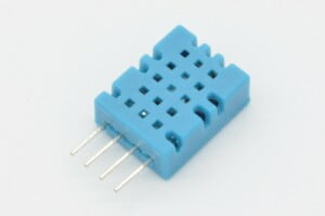
Very basic Arduino code to read a DHT11 Temperature Sensor. When the temperature drops below 0.0°C , switch on a heating pad connected to Relay #2 until the temperature rises above 0.0°C again. A 10 second delay is used to prevent rapid switching.
					#include <DHT.h>

#define DHTPIN 2       // Pin where DHT11 is connected
#define DHTTYPE DHT11  // DHT sensor type

const int heatingPadPin = 8;  // Digital pin to control Relay #2

DHT dht(DHTPIN, DHTTYPE);

void setup() {
  pinMode(heatingPadPin, OUTPUT);
  Serial.begin(9600);
  dht.begin();
}

void loop() {

  float temperature = dht.readTemperature();

  // Check if temperature is below freezing
  if (temperature < 0.0) {
    // Turn on heating pad
    digitalWrite(heatingPadPin, HIGH);
    Serial.println("Heating pad ON");
  } else {
    // Turn off heating pad
    digitalWrite(heatingPadPin, LOW);
    Serial.println("Heating pad OFF");
  }

  delay(10000);  // Adjust the delay as needed to control the update rate.
}
Schematics & Diagrams
For more information on how to use this product please check out the resources below:
Change Log
July 2020 – Version 2.0 Released
- Updated Graphics, Labeling
- Added Air Gap Isolation
- Functionally identical to previous versions.
- Image
- SKU
- Rating
- Price
- Stock
- Availability
- Add to cart
- Description
- Content
- Weight
- Dimensions
- Additional information
- Attributes
- Custom attributes
- Custom fields

