BC Robotics
2022 Holiday Gift Guide – Raspberry Pi
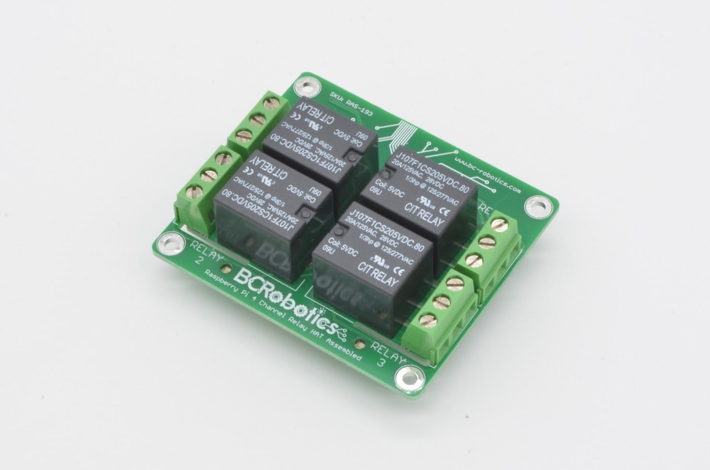


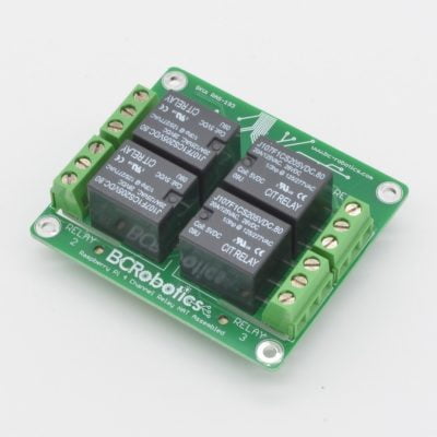
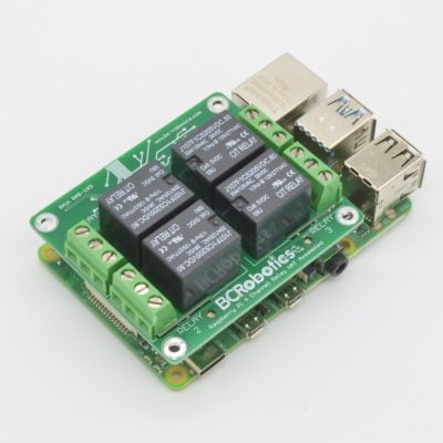
Raspberry Pi 4 Channel Relay HAT – Assembled
$24.95
Brand:
Availability:
Temporarily Out Of Stock
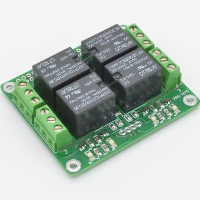
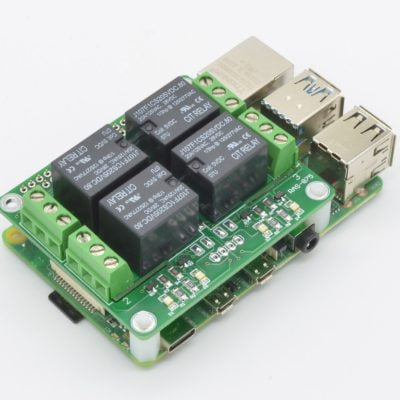
Need to drive high current or high voltage devices with your Raspberry Pi? This premium 4 channel 10A relay HAT can handle it! Each relay has the Input, Normally Open, and Normally Closed contact broken out to a nice 5mm pitch screw terminal. This HAT is compatible with the Raspberry Pi A+/B+/2/3B/3+/4 and uses GPIO pins 4, 17, 27, and 22 (Pins 7,11,13,15) on the GPIO header.
Out of Stock - Available on Backorder
Want to be notified when this product is back in stock?
Description
Need to drive high current or high voltage devices with your Raspberry Pi? This premium 4 channel 10A relay HAT can handle it! Each relay has the Input, Normally Open, and Normally Closed contact broken out to a nice 5mm pitch screw terminal. This HAT is compatible with the Raspberry Pi A+/B+/2/3B/3+/4 and uses GPIO pins 4, 17, 27, and 22 (Pins 7,11,13,15) on the GPIO header.
This version of the board is fully assembled and requires no soldering. It is compatible with all “A” and “B” versions of the Raspberry Pi (Pi A+, B+, 2, 3, 3A+, 3B+, and Pi 4)
Please Note: While this board is capable of switching higher voltages, please exercise caution. If you are inexperienced or unsure about how to use this product safely we recommend looking at the IoT Power Relay, which has all of its high voltage circuitry fully enclosed.
Features
- Fits directly on the Pi 40 pin GPIO header
- Fully Assembled - no soldering required!
- Switch up to 10A per channel!
- UL 94V-0 flammability rated PCB
Package Contents
- 1 x Raspberry Pi 4 Channel Relay HAT - Assembled
May We Also Suggest…
Tutorial
Product Tutorial: https://bc-robotics.com/tutorials/getting-started-raspberry-pi-relay-hat/Warranty Policy
This product has a 30 Day Warranty from the date of delivery. The item must not be modified, abused, incorrectly hooked up, or used for purposes outside the original scope of design.
Return Policy
This product is returnable Within 14 Days of delivery for a store credit. Item must be unopened, unused, and in re-saleable condition.
More Information:
For more information on our Warranty and Return Policies, please consult our Terms of ServiceComments
There are no comments yet.
Related Products


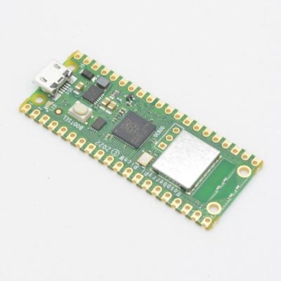
Raspberry Pi Pico
$8.95
Availability:
Low Stock - Only 2 Remaining
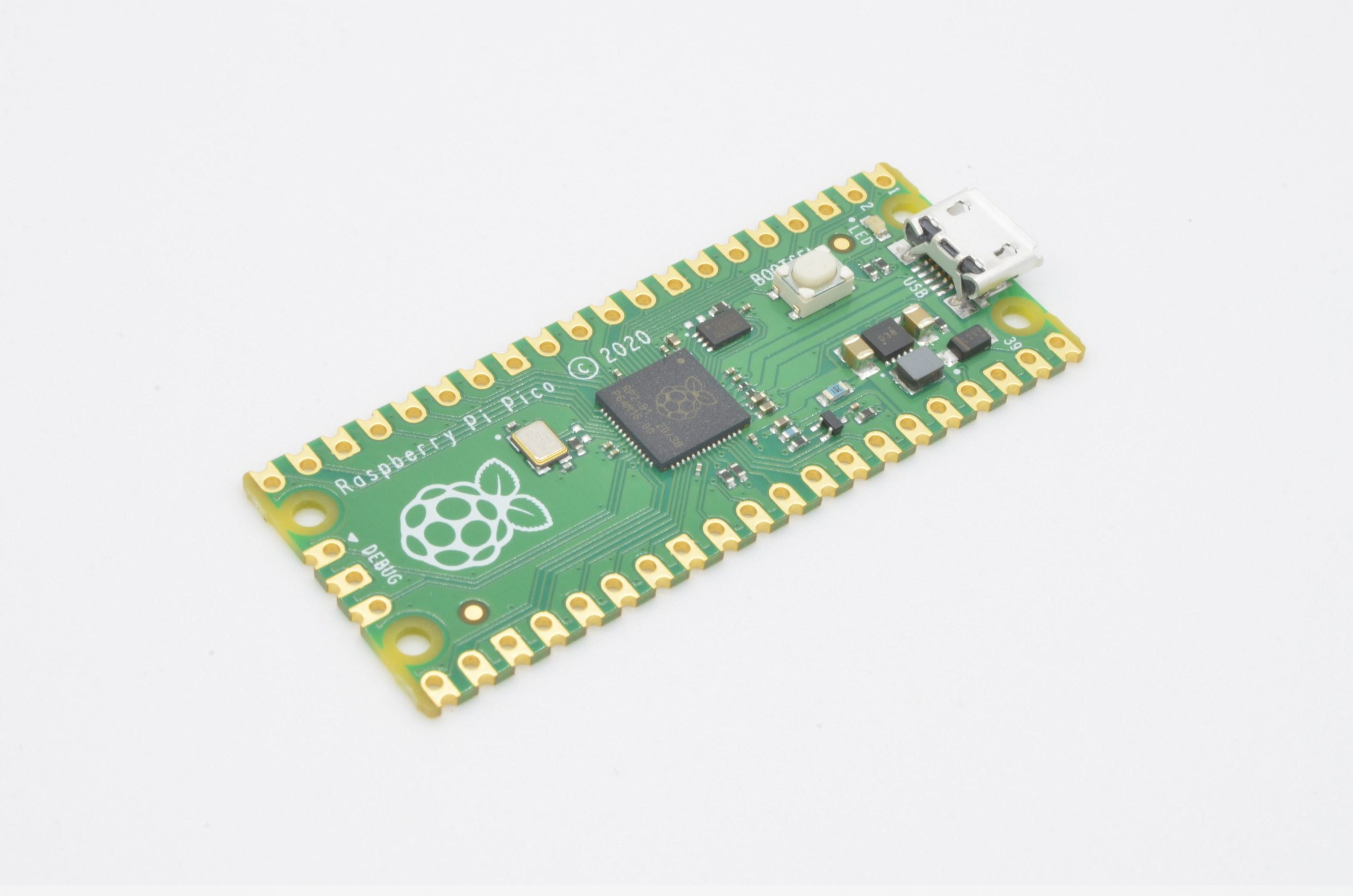
The Raspberry Pi Pico is the first microcontroller developed by the Raspberry Pi Foundation. It features their own in-house designed chip, the RP2040. It is a low-cost, high performance controller designed with Python in mind. It is easy to use and features a full getting started guide care of the Pi Foundation.
Available
Description
The Raspberry Pi Pico is a low-cost, high-performance microcontroller board with flexible digital interfaces. It features the RP2040 which marks Raspberry Pi’s first microcontroller designed in-house. Pico provides minimal (yet flexible) external circuitry to support the RP2040 chip (Flash, crystal, power supplies and decoupling and USB connector). The majority of the RP2040 microcontroller pins are brought to the user IO pins on the left and right edge of the board. Four RP2040 IO are used for internal functions – driving an LED, on-board Switched Mode Power Supply (SMPS) power control and sensing the system voltages.
Pico uses an on-board buck-boost SMPS which is able to generate the required 3.3 volts (to power RP2040 and external circuitry) from a wide range of input voltages (~1.8 to 5.5V). This allows significant flexibility in powering the unit from various sources such as a single Lithium-Ion cell, or 3 AA cells in series. Battery chargers can also be very easily integrated with the Pico powerchain. Reprogramming the Pico’s flash memory can be done using USB (simply drag and drop a file onto the Pico which appears as a mass storage device) or via the Serial Wire Debug (SWD) port. The SWD port can also be used to interactively debug code running on the RP2040
Pico has been designed to use either soldered 0.1″ pin-headers (it is one 0.1″ pitch wider than a standard 40-pin DIP package) or can be used as a surface mountable “module”, as the user IO pins are also castellated. There are SMT pads underneath the USB connector and BOOTSEL button, which allow these signals to be accessed if used as a reflow-soldered SMT module.
Features
- RP2040 microcontroller chip designed by Raspberry Pi
- Flexible clock running up to 133 MHz
- 264kB of SRAM
- Low-power sleep and dormant modes
- 26 multi-function GPIO pins
- 16 x PWM Outputs
- Accurate clock and timer on-chip
- Accelerated floating point libraries on-chip
- Dual-core ARM Cortex M0+ processor
- 2MB of on-board Flash memory
- USB 1.1 Host and Device support
- Drag & drop programming using mass storage over USB
- 3 x 12-bit Analog Input
- 2× SPI, 2× I2C, 2× UART
- Temperature sensor
- 8 × Programmable IO (PIO) state machines for custom peripheral support
Package Contents
- 1 x Raspberry Pi Pico
May We Also Suggest…


Tutorial
Product Tutorial: http://www.raspberrypi.org/documentation/pico/getting-startedOnline Guide
Online Guide: https://learn.adafruit.com/getting-started-with-raspberry-pi-pico-circuitpythonWarranty Policy
This product has a 30 Day Warranty from the date of delivery. The item must not be modified, abused, incorrectly hooked up, or used for purposes outside the original scope of design.
Return Policy
This product is returnable Within 14 Days of delivery for a store credit. Item must be unopened, unused, and in re-saleable condition.
More Information:
For more information on our Warranty and Return Policies, please consult our Terms of ServiceComments
There are no comments yet.
Related Products


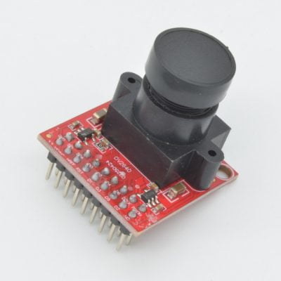
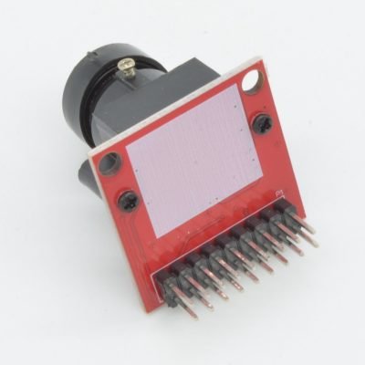
Raspberry Pi Zero Mini Camera – 5MP
$19.95
Availability:
Low Stock - Only 2 Remaining
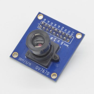
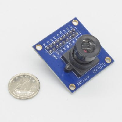
This tiny camera is perfectly suited to the Pi Zero! The camera features an OV5647 image sensor rated at 5MP and an incredibly small form factor.
Available
Description
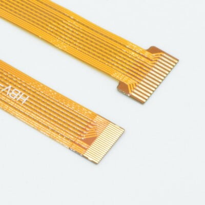
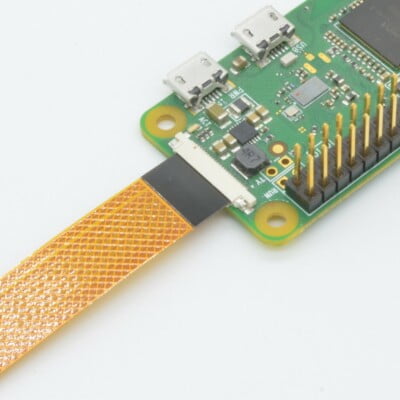
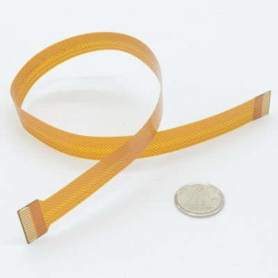
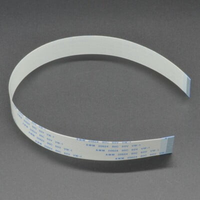
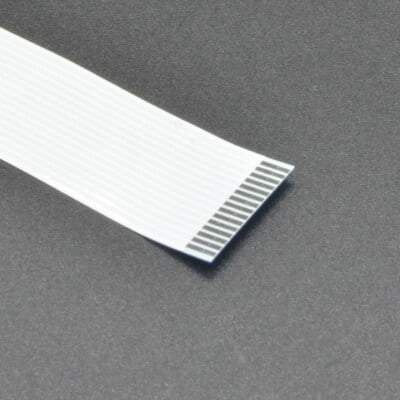
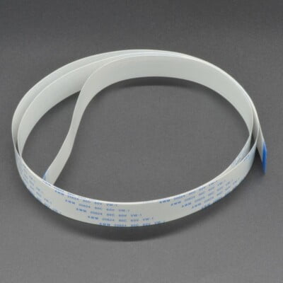
This tiny camera is perfectly suited to the Pi Zero! The camera features an OV5647 image sensor rated at 5MP and an incredibly small form factor. The camera itself measures 9 x 9mm and is equipped with the smaller style CSI cable found on the Pi Zero (1.3 and newer), so no adapters are required to use it. Because of this cable size, the camera is not compatible with standard Raspberry Pi.
The camera has a fixed focal length and a field of view measuring 72.4 degrees. On the back of the camera and cable, included double sided foam sticky tape will help keep it in place!
Please Note: Raspberry Pi Zero sold separately.
Features
- Resolution: 5 Megapixel
- Camera Dimensions: 9 x 9mm
- Camera Height: 6mm
- Designed for Raspberry Pi Zero
- CCD size: 0.25˝
- Field of View: 72.4 degrees
- Image Sensor: OV5647
- Cable Length: 50mm
Package Contents
- 1 x Raspberry Pi Zero Mini Camera - 5MP
May We Also Suggest…
Warranty Policy
This product has a 30 Day Warranty from the date of delivery. The item must not be modified, abused, incorrectly hooked up, or used for purposes outside the original scope of design.
Return Policy
This product is returnable Within 14 Days of delivery for a store credit. Item must be unopened, unused, and in re-saleable condition.
More Information:
For more information on our Warranty and Return Policies, please consult our Terms of ServiceComments
There are no comments yet.
Related Products


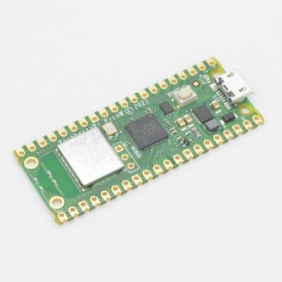
Raspberry Pi Pico W
$11.95
Availability:
Low Stock - Only 1 Remaining
The Raspberry Pi Pico W is the WiFi enabled version of the popular Pico microcontroller developed by the Raspberry Pi Foundation. It features their own in-house designed chip, the R2040 and an Infineon CYW43439 wireless chip. Ideal for Internet of Things (IoT) applications. It is easy to use and features a full getting started guide care of the Pi Foundation.
Please Note: Limit 1 Per Customer
Available
Description
The Raspberry Pi Pico W is the WiFi enabled version of this popular Raspberry Pi microcontroller. This new version adds an Infineon CYW43439 wireless chip. The CYW43439 supports 802.11 b/g/n wireless LAN and turns the Pico into an ideal board for IoT applications.
The Pico W utilizes the RP2040 which marks Raspberry Pi’s first microcontroller designed in-house. Pico provides minimal (yet flexible) external circuitry to support the RP2040 chip (Flash, crystal, power supplies and decoupling and USB connector). The majority of the RP2040 microcontroller pins are brought to the user IO pins on the left and right edge of the board. Four RP2040 IO are used for internal functions – driving an LED, on-board Switched Mode Power Supply (SMPS) power control and sensing the system voltages.
Pico uses an on-board buck-boost SMPS which is able to generate the required 3.3 volts (to power RP2040 and external circuitry) from a wide range of input voltages (~1.8 to 5.5V). This allows significant flexibility in powering the unit from various sources such as a single Lithium-Ion cell, or 3 AA cells in series. Battery chargers can also be very easily integrated with the Pico powerchain. Reprogramming the Pico’s flash memory can be done using USB (simply drag and drop a file onto the Pico which appears as a mass storage device) or via the Serial Wire Debug (SWD) port. The SWD port can also be used to interactively debug code running on the RP2040
Pico has been designed to use either soldered 0.1″ pin-headers (it is one 0.1″ pitch wider than a standard 40-pin DIP package) or can be used as a surface mountable “module”, as the user IO pins are also castellated. There are SMT pads underneath the USB connector and BOOTSEL button, which allow these signals to be accessed if used as a reflow-soldered SMT module.
Features
- RP2040 microcontroller chip designed by Raspberry Pi
- CYW43439 wireless chip
- 802.11 b/g/n wireless LAN
- Flexible clock running up to 133 MHz
- 264kB of SRAM
- Low-power sleep and dormant modes
- 26 multi-function GPIO pins
- 16 x PWM Outputs
- Accurate clock and timer on-chip
- Accelerated floating point libraries on-chip
- Dual-core ARM Cortex M0+ processor
- 2MB of on-board Flash memory
- USB 1.1 Host and Device support
- Drag & drop programming using mass storage over USB
- 3 x 12-bit Analog Input
- 2× SPI, 2× I2C, 2× UART
- Temperature sensor
- 8 × Programmable IO (PIO) state machines for custom peripheral support
Package Contents
- 1 x Raspberry Pi Pico W
May We Also Suggest…
Tutorial
Product Tutorial: http://www.raspberrypi.org/documentation/pico/getting-startedOnline Guide
Online Guide: https://learn.adafruit.com/getting-started-with-raspberry-pi-pico-circuitpythonWarranty Policy
This product has a 30 Day Warranty from the date of delivery. The item must not be modified, abused, incorrectly hooked up, or used for purposes outside the original scope of design.
Return Policy
This product is returnable Within 14 Days of delivery for a store credit. Item must be unopened, unused, and in re-saleable condition.
More Information:
For more information on our Warranty and Return Policies, please consult our Terms of ServiceComments
There are no comments yet.
Related Products
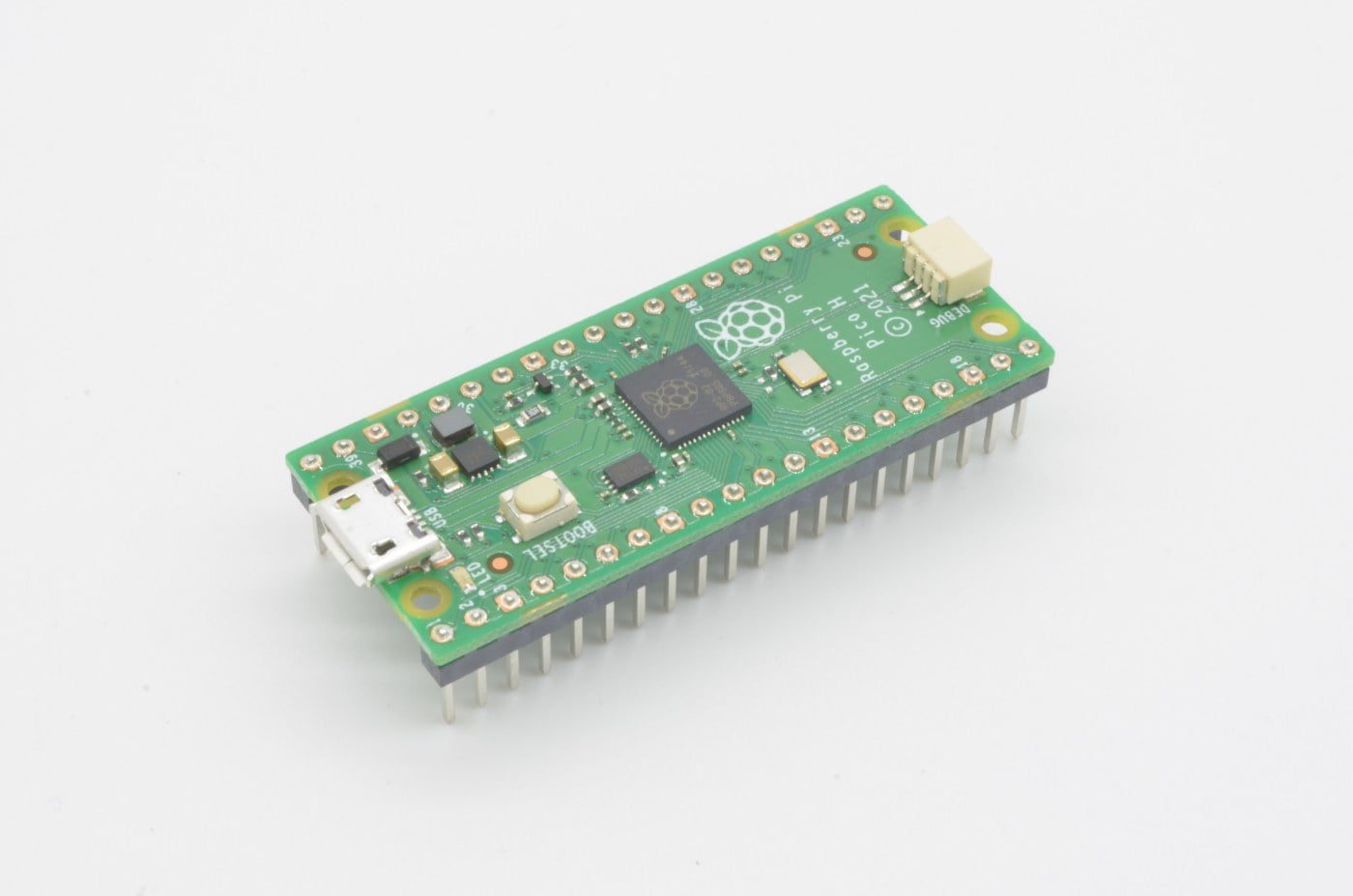


Raspberry Pi Pico H
$9.95
Availability:
Low Stock - Only 1 Remaining
The Raspberry Pi Pico H is a no-soldering-required version of the standard Raspberry Pi Pico. It features pre-soldered breadboard compatible headers, making this ready to use right out of the package.
Available
Description
The Raspberry Pi Pico H is a no-soldering-required version of the standard Raspberry Pi Pico. It features pre-soldered breadboard compatible headers, making this ready to use right out of the package. Pico provides minimal (yet flexible) external circuitry to support the RP2040 chip (Flash, crystal, power supplies and decoupling and USB connector). The majority of the RP2040 microcontroller pins are brought to the user IO pins on the left and right edge of the board. Four RP2040 IO are used for internal functions – driving an LED, on-board Switched Mode Power Supply (SMPS) power control and sensing the system voltages.
Pico uses an on-board buck-boost SMPS which is able to generate the required 3.3 volts (to power RP2040 and external circuitry) from a wide range of input voltages (~1.8 to 5.5V). This allows significant flexibility in powering the unit from various sources such as a single Lithium-Ion cell, or 3 AA cells in series. Battery chargers can also be very easily integrated with the Pico powerchain. Reprogramming the Pico’s flash memory can be done using USB (simply drag and drop a file onto the Pico which appears as a mass storage device) or via the Serial Wire Debug (SWD) port. The SWD port can also be used to interactively debug code running on the RP2040.
The Pico H has pre-soldered 0.1″ pin-headers and will slot right into a breadboard (it is one 0.1″ pitch wider than a standard 40-pin DIP package).
Features
- RP2040 microcontroller chip designed by Raspberry Pi
- Flexible clock running up to 133 MHz
- 264kB of SRAM
- Low-power sleep and dormant modes
- 26 multi-function GPIO pins
- 16 x PWM Outputs
- Accurate clock and timer on-chip
- Accelerated floating point libraries on-chip
- Dual-core ARM Cortex M0+ processor
- 2MB of on-board Flash memory
- USB 1.1 Host and Device support
- Drag & drop programming using mass storage over USB
- 3 x 12-bit Analog Input
- 2× SPI, 2× I2C, 2× UART
- Temperature sensor
- 8 × Programmable IO (PIO) state machines for custom peripheral support
- No soldering required!
Package Contents
- 1 x Raspberry Pi Pico H
May We Also Suggest…
Tutorial
Product Tutorial: http://www.raspberrypi.org/documentation/pico/getting-startedOnline Guide
Online Guide: https://learn.adafruit.com/getting-started-with-raspberry-pi-pico-circuitpythonWarranty Policy
This product has a 30 Day Warranty from the date of delivery. The item must not be modified, abused, incorrectly hooked up, or used for purposes outside the original scope of design.
Return Policy
This product is returnable Within 14 Days of delivery for a store credit. Item must be unopened, unused, and in re-saleable condition.
More Information:
For more information on our Warranty and Return Policies, please consult our Terms of ServiceComments
There are no comments yet.
Related Products


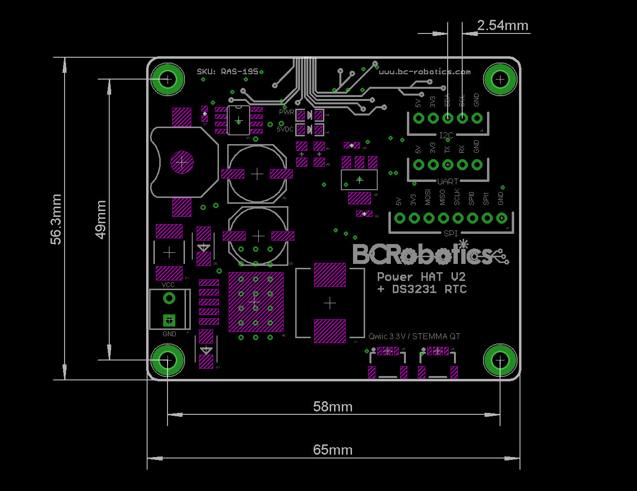
Raspberry Pi Power + RTC HAT – Assembled
$41.95
Brand:
Availability:
Temporarily Out Of Stock
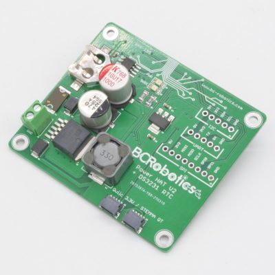
The Raspberry Pi Power RTC HAT is an all in one DC/DC converter and accurate DS3231 Real Time Clock. The fused and reverse polarity protected DC input is coupled to a beefy 3A 5V DC/DC converter. Connected to a 12V automotive battery, this board is happy running the Pi under heavy load all day long.
Out of Stock - Available on Backorder
Want to be notified when this product is back in stock?
Description
Two of the biggest challenges with the Raspberry Pi in portable/mobile/automotive applications is the lack of an accurate way to keep time and a flexible input DC power supply. This Raspberry Pi Power / RTC HAT solves this problem! Onboard is a fused and reverse polarity protected DC input coupled to a beefy 3A 5V DC/DC converter. Connected to a 12V automotive battery, this board is happy running the Pi under heavy load all day long.
Since a battery powered Pi is not likely going to have reliable access to the internet to keep time we have also added a nice, temperature compensated, DS3231 chipset by Maxim. The chip is connected directly to the I2C bus and uses address 0x68. Simply add a CR1220 battery to the holder onboard, set the time, and it will keep it within ±0.432 Second/Day (roughly ±2 minutes a year) in temperatures ranging between -45°C and +85°C.
To make this board even more useful, we have also included two SparkFun Qwiic / Adafruit STEMMA QT connectors – this is an easy-connect system for I2C sensors, actuators, shields using pre-built cables that make prototyping faster and less prone to error. Add sensors and further expand your Pi’s monitoring and control capabilities as you need, with no soldering required.
This version is fully assembled – no soldering required. Just hook it up and you are good to go! The board is compatible with all “A” and “B” versions of the Raspberry Pi (Pi A+, B+, 2, 3, 3A+, 3B+, and Pi 4)
Please Note: Raspberry Pi not included.
Features
- RTC Accuracy of ±0.432 Second/Day
- Two STEMMA QT / Qwiic connectors
- Two Time-of-Day Alarms
- RTC Battery Backup: CR1220
- 5V 3A Output to power Raspberry Pi
- Dimensions: 65 x 56mm
- Leap-Year Compensation Up to Year 2100
- Separate onboard 3.3V Regulator for Qwiic / STEMMA QT Bus
- Complete Clock Calendar Functionality
- Maximum Regulator Input: 36VDC
- Recommended Input: 7 - 16VDC
- Height: 12mm
- UL 94V-0 flammability rated PCB
Package Contents
- 1 x Raspberry Pi Power + RTC HAT - Assembled
May We Also Suggest…
Tutorial
Product Tutorial: https://bc-robotics.com/tutorials/getting-started-power-hats/Online Guide
Online Guide: https://learn.adafruit.com/adding-a-real-time-clock-to-raspberry-pi/set-up-and-test-i2cMechanical Drawing
Mechanical Drawing: https://bc-robotics.com/wp-content/uploads/2024/03/raspberry-pi-power-rtc-hat-assembled-drawing.pngWarranty Policy
This product has a 30 Day Warranty from the date of delivery. The item must not be modified, abused, incorrectly hooked up, or used for purposes outside the original scope of design.
Return Policy
This product is returnable Within 14 Days of delivery for a store credit. Item must be unopened, unused, and in re-saleable condition.
More Information:
For more information on our Warranty and Return Policies, please consult our Terms of ServiceComments
You may also like…

Related Products


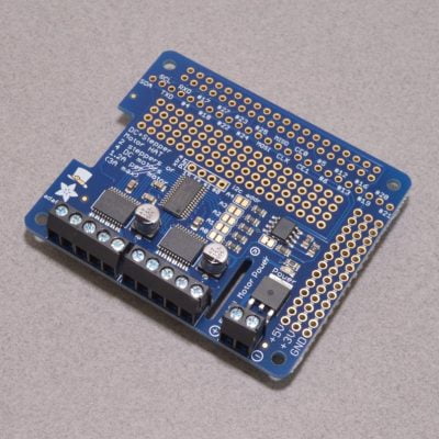
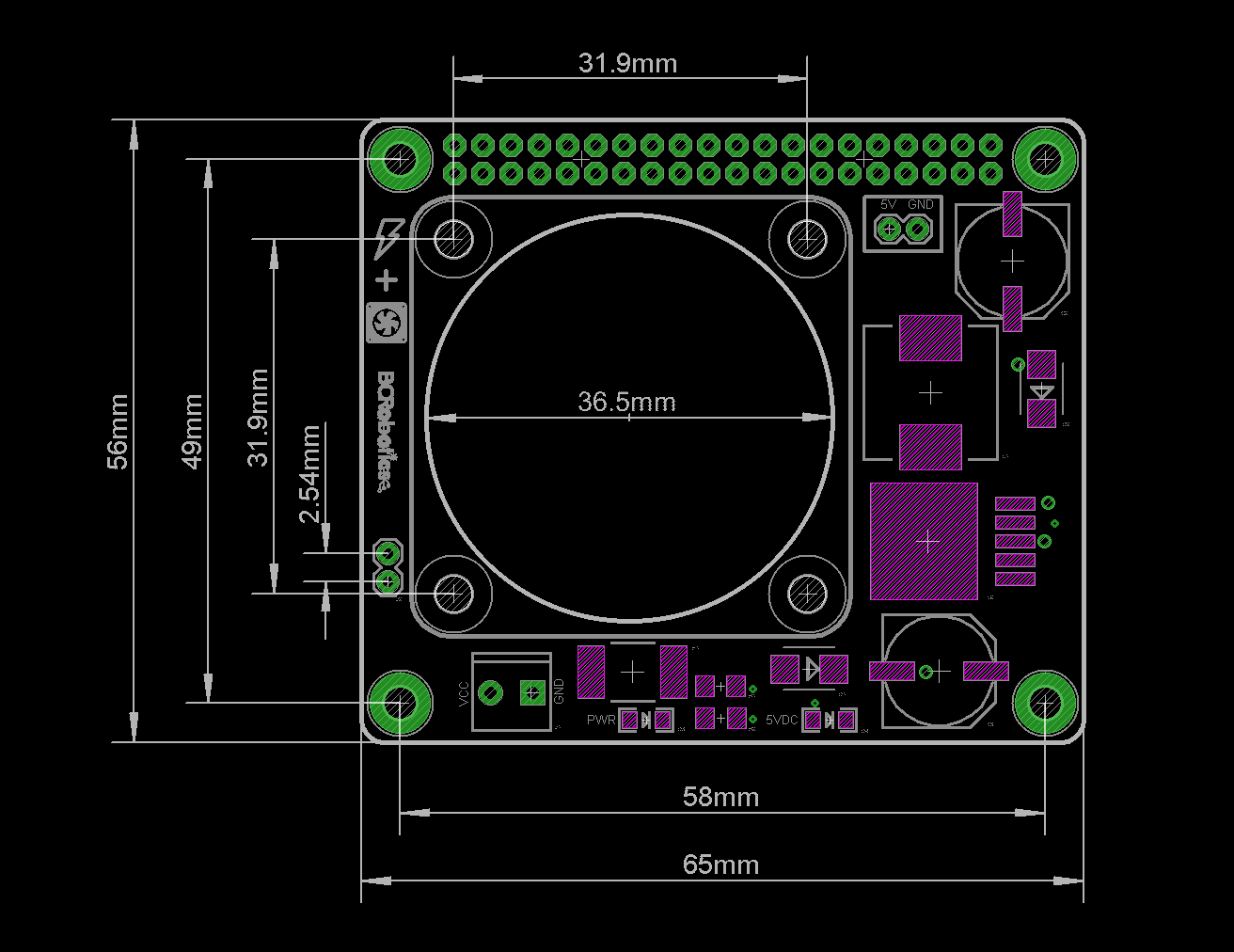
Raspberry Pi Power + Fan HAT – Assembled
$25.95
Brand:
Availability:
Low Stock - Only 2 Remaining
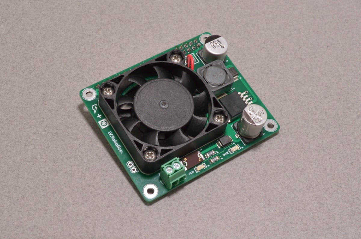
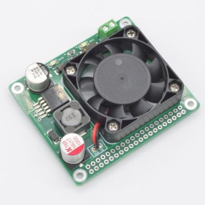
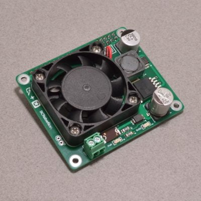
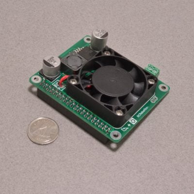
The Raspberry Pi Power / Fan HAT is a combination of two of our most popular Raspberry Pi add-ons. This board is based on the same beefy 3A 5V DC/DC converter found on our Power and Power RTC HAT and features the same 40mm fan used on our Fan HAT. Combined, this will comfortably power your Pi from 7-16V while keeping it cool under heavy load.
Available
Description
The Raspberry Pi Power / Fan HAT is a combination of two of our most popular Raspberry Pi add-ons. This board is based on the same beefy 3A 5V DC/DC converter found on our Power and Power RTC HAT and features the same 40mm fan used on our Fan HAT. Combined, this will comfortably power your Pi from 7-16V while keeping it cool under heavy load.
The power supply is fused and reverse polarity protected and provides power to the Pi by way of the GPIO header. The Fan runs as long as power is available. Simply connect your DC supply to the screw terminals and this board will keep your Pi3 / 3+ / 4 happy running under heavy load all day long! We recommend keeping the input voltage to 7-16VDC to prevent the regulator from getting too warm.
Finally, we have also added an optional 2 pin footprint on the board for a 2.54mm / 0.100” connector for use as a soft shutdown / restart. With dtoverlay=gpio-shutdown enabled in your /boot/config.txt file, connecting these two pins will trigger the Pi to perform a shutdown. Press the button again, and the Pi will boot right up. We recommend using a momentary pushbutton for this feature. At this time, the Pi 4 is only capable of shutdown and will not restart without modifying the bootloader.
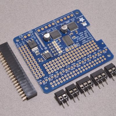
This version of the board is fully assembled and requires no soldering. If you prefer to choose your own 2×20 header, we also have the Pi Power / Fan HAT available with no header attached.
Please Note: Raspberry Pi is sold separately.
Features
- 5V 3A Output to power Raspberry Pi
- Integrated 40mm Fan
- Pi 3 / 3A+ / 3B+ / Pi 4 Compatible
- Connector for shutdown / restart button
- No Soldering Required!
- Fused and Reverse Polarity Protected
- Recommended Input: 7 - 16VDC
- Ideal for 12V power systems
- Fully assembled and ready to use!
- UL 94V-0 flammability rated PCB
Package Contents
- 1 x Raspberry Pi Power + Fan HAT - Assembled
May We Also Suggest…
Tutorial
Product Tutorial: https://bc-robotics.com/tutorials/getting-started-power-hats/Mechanical Drawing
Mechanical Drawing: https://bc-robotics.com/wp-content/uploads/2024/03/raspberry-pi-power-fan-hat.pngWarranty Policy
This product has a 30 Day Warranty from the date of delivery. The item must not be modified, abused, incorrectly hooked up, or used for purposes outside the original scope of design.
Return Policy
This product is returnable Within 14 Days of delivery for a store credit. Item must be unopened, unused, and in re-saleable condition.
More Information:
For more information on our Warranty and Return Policies, please consult our Terms of ServiceComments
-

Any opportunity for this to send the same soft shutdown automatically if it detects low input voltage vs needing a momentary switch?
-
Hi Jeremy,
Thanks for the note – not within the board itself as the Pi wouldn’t be able to detect the voltage itself. You would need an analog to digital converter and voltage divider (at a minimum) to read the voltage itself on the input, and a larger capacitor bank to provide enough time for everything to occur in the shutdown process. You could add the additional components to a proto HAT and stack this on top (in theory). Hope that helps!
-
-
Does the fan stop when you shut down the pi? or does it just stay on as long as power is connected?
-
Hi Tristan,
The fan will run as long as there is power to this board – let us know if you have further questions!
-
-
Hello,
This is a good board for my use. Can you tell me which GPIO pins the “Shutdown” button uses?
I was reading another article (https://learn.sparkfun.com/tutorials/raspberry-pi-safe-reboot-and-shutdown-button/all) that suggests using a pull up resistor ro the pins arent floating. Do you have any comments? I will be experimenting later today.
Thanks you in advance,
…Brent…
Victoria, BC-
Hi Brent!
GPIO 3 is pulled out to the footprint on the board. When using the
dtoverlay=gpio-shutdownin your config.txt as a method of control, the GPIO is pulled high and shorted to ground to reset so no resistor is required.
-
You may also like…
Raspberry Pi Power + RTC HAT
$34.95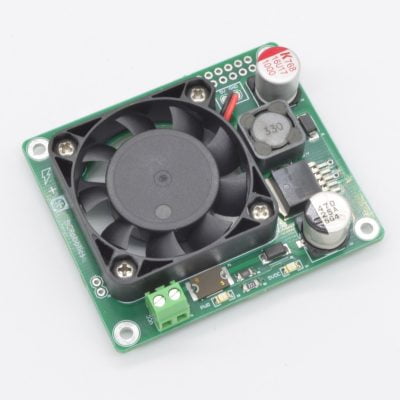
Related Products
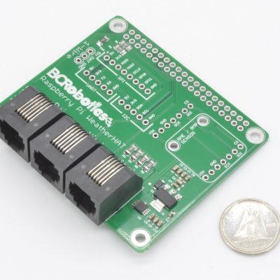
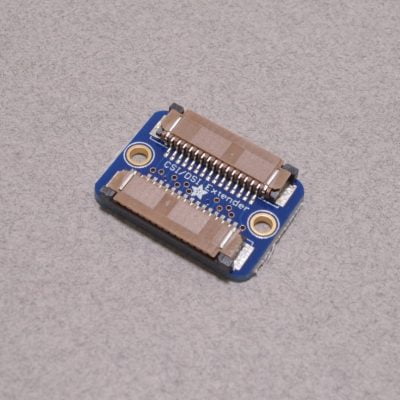
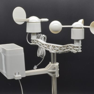
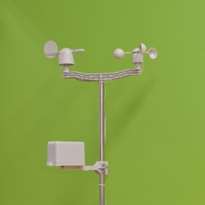
Raspberry Pi Weather Board
$22.95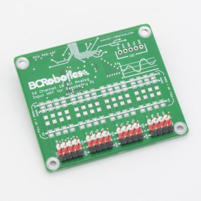
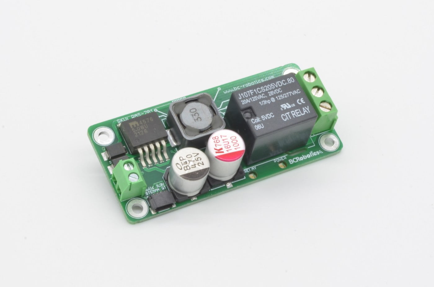


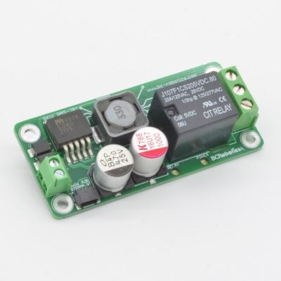
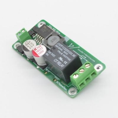
Raspberry Pi Zero Power + Relay HAT
$24.95
Brand:
Availability:
Temporarily Out Of Stock
The Raspberry Pi Zero Power + Relay HAT is designed as an all-in-one simple automation add on for the Raspberry Pi Zero. It combines the beefy 5V 3A power supply from our series of Raspberry Pi Power HAT with a 10A relay and a Qwiic / STEMMA QT port.
Out of Stock - Available on Backorder
Want to be notified when this product is back in stock?
Description
The Raspberry Pi Zero Power + Relay HAT is designed as an all-in-one simple automation add on for the Raspberry Pi Zero. It combines the beefy 5V 3A power supply from our series of Raspberry Pi Power HAT with a 10A relay. These are ideal for situations where 7-16V DC power is readily available and higher voltage / current loads need to be switched.
To add to the functionality, we have also included an Adafruit STEMMA QT / SparkFun Qwiic socket so additional Qwiic / STEMMA QT sensors and breakout boards can be added with ease!
This HAT is compatible with the Raspberry Pi Zero / Zero 1.3 / Zero W / Pi 2W and uses GPIO pins 4 (Pin 7) on the GPIO header. The board is fully assembled with a Raspberry Pi GPIO header, meaning no soldering required for Pi Zeros with the mating headers already installed!
Features
- Fits directly on the Pi 40 pin GPIO header
- Relay on GPIO 4
- No Soldering Required
- Compatible with all models of the Raspberry Pi Zero
- Switch up to 10A
- 5V 3A Output to power Raspberry Pi
- Fused and Reverse Polarity Protected Power Input
- Recommended Input: 7 - 16VDC
- Ideal for 12V power systems
- UL 94V-0 flammability rated PCB
Package Contents
1 x Raspberry Pi Zero Power + Relay HATMay We Also Suggest…
Warranty Policy
This product has a 30 Day Warranty from the date of delivery. The item must not be modified, abused, incorrectly hooked up, or used for purposes outside the original scope of design.
Return Policy
This product is returnable Within 14 Days of delivery for a store credit. Item must be unopened, unused, and in re-saleable condition.
More Information:
For more information on our Warranty and Return Policies, please consult our Terms of ServiceComments
-
What is the duty cycle of the relay? Can it be turned on and remain on for several hours?
I want to use it to control a cooling fan for an MPPT Charge Controller. Thank You!-
Hi Keith,
These will handle 100% duty cycle – shouldn’t be an issue.
-
Related Products


Raspberry Pi Zero Relay HAT – Assembled
$18.95
Brand:
Availability:
Temporarily Out Of Stock
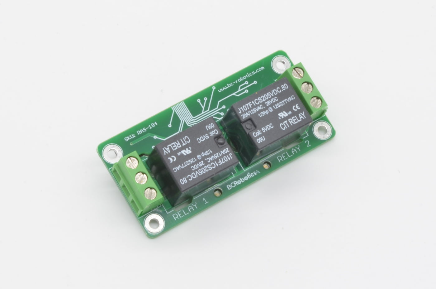
With the addition of WiFi and Bluetooth to the Raspberry Pi Zero W, it is now finding itself in many more IoT applications. This assembled 2 Channel Relay HAT makes driving higher current and higher voltage devices as easy as possible! This premium Relay HAT matches the Raspberry Pi Zero form factor and is compatible with all versions of the Pi Zero.
Out of Stock - Available on Backorder
Want to be notified when this product is back in stock?
Description
With the addition of WiFi and Bluetooth to the Raspberry Pi Zero W, it is now finding itself in many more IoT applications. This assembled 2 Channel Relay HAT makes driving higher current and higher voltage devices as easy as possible! This premium Relay HAT matches the Raspberry Pi Zero form factor and is compatible with all versions of the Pi Zero. Each 10A relay has the Input, Normally Open, and Normally Closed contact broken out to a nice 5mm pitch screw terminal. The board uses high quality North American sourced parts, a locally produced circuit board, and simple logic level inputs.
This HAT is compatible with the Raspberry Pi Zero / Zero 1.3 / Zero W and uses GPIO pins 4 and 17 (Pins 7 & 11) on the GPIO header. The pre-installed Raspberry Pi GPIO header means this is plug and play – no soldering required for Pi Zeros with the mating headers already installed!
Please Note: While this board is capable of switching higher voltages, please exercise caution. If you are inexperienced or unsure about how to use this product safely we recommend looking at the IoT Power Relay, which has all of its high voltage circuitry fully enclosed.
Features
- Fits directly on the Pi 40 pin GPIO header
- Uses GPIO 4 and GPIO 17
- No Soldering Required
- Switch up to 10A per channel!
- Compatible with all models of the Raspberry Pi Zero
- UL 94V-0 flammability rated PCB
Package Contents
- 1 x Raspberry Pi Zero Relay HAT - Assembled
Tutorial
Product Tutorial: https://bc-robotics.com/tutorials/getting-started-raspberry-pi-relay-hat/Warranty Policy
This product has a 30 Day Warranty from the date of delivery. The item must not be modified, abused, incorrectly hooked up, or used for purposes outside the original scope of design.
Return Policy
This product is returnable Within 14 Days of delivery for a store credit. Item must be unopened, unused, and in re-saleable condition.
More Information:
For more information on our Warranty and Return Policies, please consult our Terms of ServiceComments
There are no comments yet.
Related Products


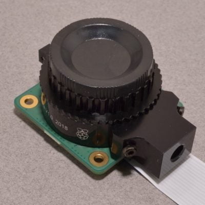
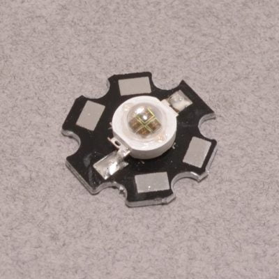
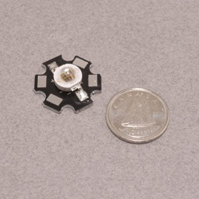
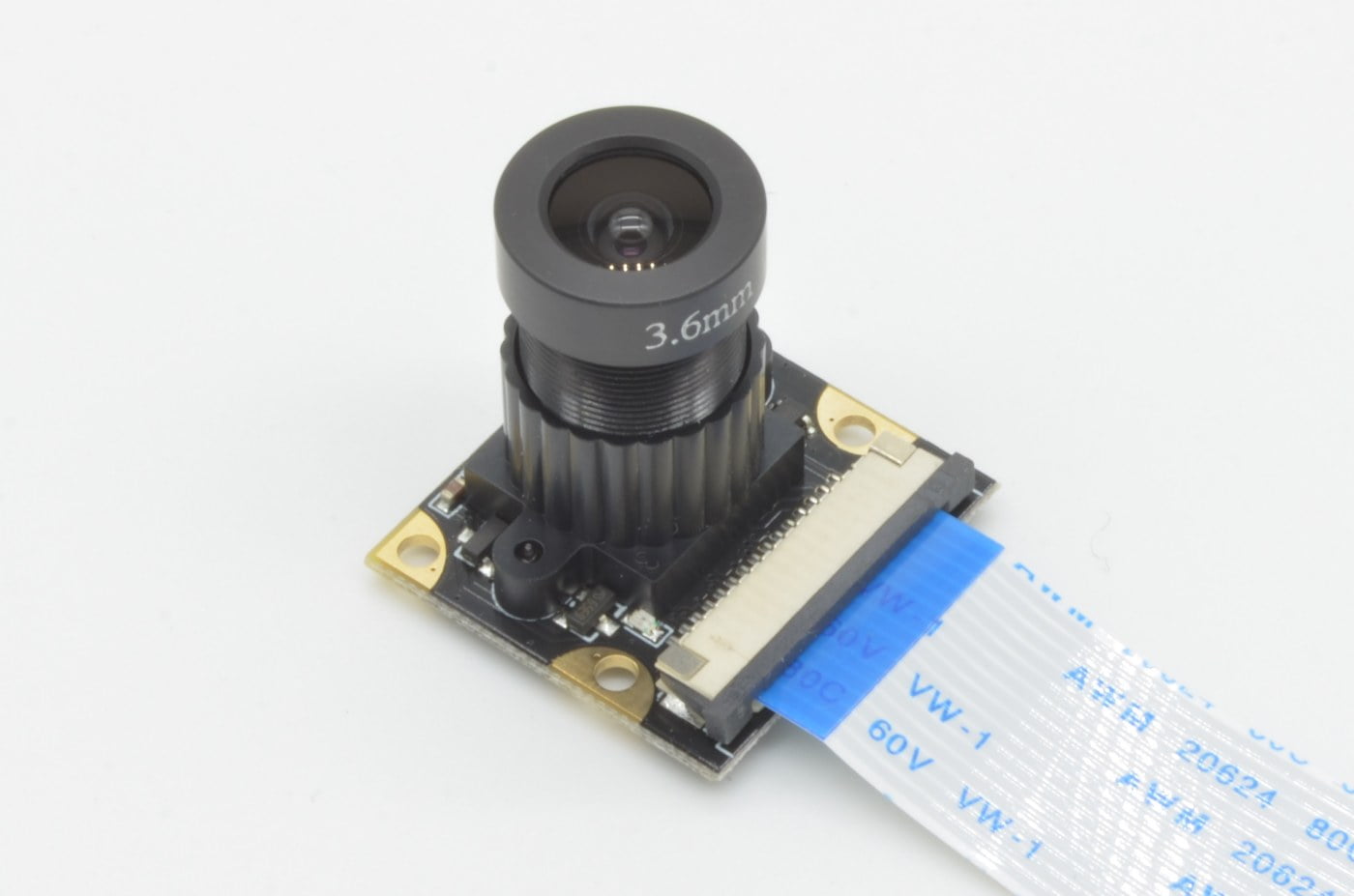
Raspberry Pi Wide Angle NoIR Camera
$26.95
Availability:
In Stock
This wide-angle Raspberry Pi camera features the same OVR5647 5 megapixel camera found in the Official Raspberry Pi Camera V1. The field of view is significantly wider due to a 130 degree FOV wide angle lens with adjustable focus.
Available
Description
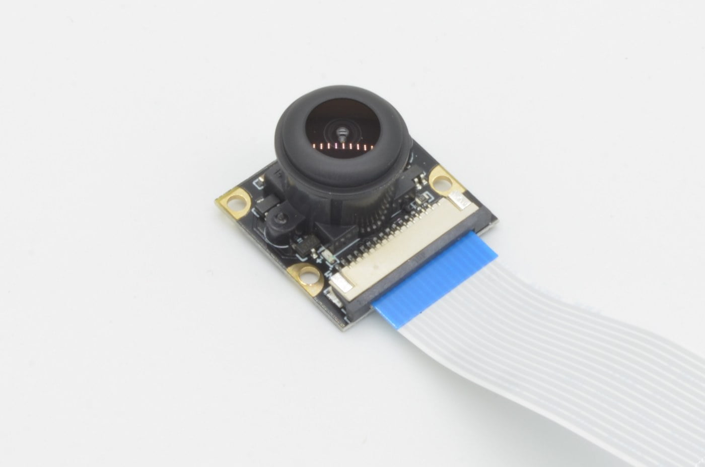
This wide-angle Raspberry Pi camera features the same OVR5647 5 megapixel camera found in the Official Raspberry Pi Camera V1 with a few improvements. The field of view is significantly wider due to a 130 degree FOV wide angle lens with adjustable focus. The camera also features two mounting points for Infrared Spotlights – these mount directly to the camera and are powered from the Pi.
The camera itself measures 25 x 24mm and 19mm tall with a 145mm (~5.5 inch) cable. The cable will connect directly to any standard sized Raspberry Pi (A, B, A+, B+, 2, 3, 3A+, 3B+, or any of the Raspberry Pi 4)
Please Note: Raspberry Pi sold separately.
Features
- Resolution: 5 Megapixel (2592x1944)
- Camera Dimensions: 25 x 24mm
- Camera Height: 19mm
- Focal Length : 3.6mm (adjustable)
- Designed for Raspberry Pi
- Cable Length: 145mm
- Video frame rate: 1080p 30fps (H.264 AVC)
- Up to 90 fps Video at VGA
- CCD size: 0.25˝
- Field of View: 130 degrees
- Image Sensor: OV5647
Package Contents
- 1 x Raspberry Pi Wide Angle NoIR Camera
- 1 x 145mm Camera Cable
May We Also Suggest…
Warranty Policy
This product has a 30 Day Warranty from the date of delivery. The item must not be modified, abused, incorrectly hooked up, or used for purposes outside the original scope of design.
Return Policy
This product is returnable Within 14 Days of delivery for a store credit. Item must be unopened, unused, and in re-saleable condition.
More Information:
For more information on our Warranty and Return Policies, please consult our Terms of ServiceComments
There are no comments yet.
Related Products
-
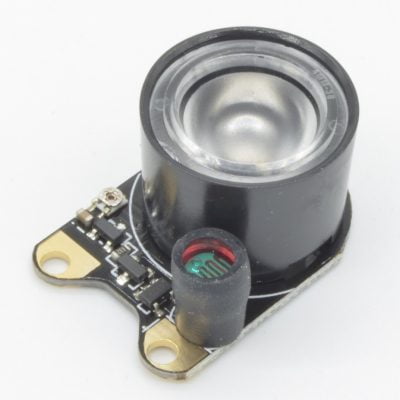
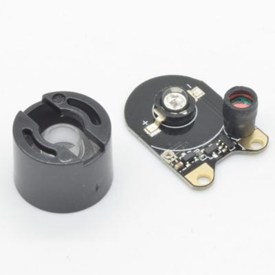
Infrared Spotlight
$5.95 -
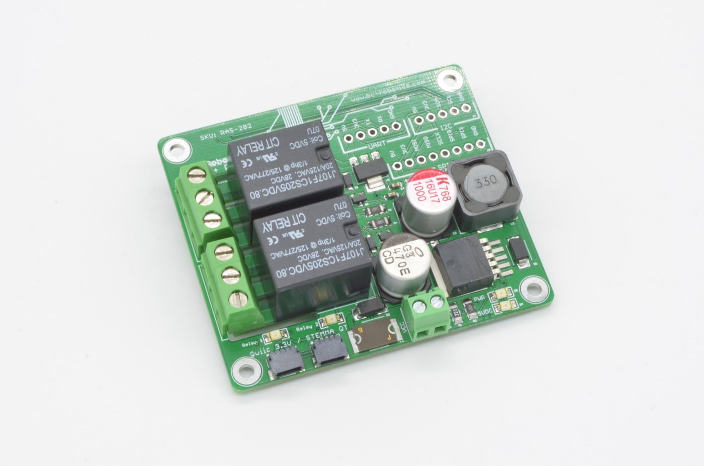


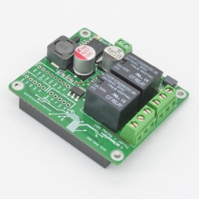
Raspberry Pi Power + Relay HAT
$33.95
Brand:
Availability:
Temporarily Out Of Stock
The Raspberry Pi Power + Relay HAT is designed as an all-in-one simple automation add on for Raspberry Pi. It combines the beefy 5V 3A power supply from our series of Raspberry Pi Power HAT with two 10A relays. These are ideal for situations where 7-16V DC power is readily available and higher voltage / current loads need to be switched.
Out of Stock - Available on Backorder
Want to be notified when this product is back in stock?
Description
The Raspberry Pi Power + Relay HAT is designed as an all-in-one simple automation add on for Raspberry Pi. It combines the beefy 5V 3A power supply from our series of Raspberry Pi Power HAT with two 10A relays. These are ideal for situations where 7-16V DC power is readily available and higher voltage / current loads need to be switched.
To add to the functionality, we have also included a pair of Adafruit STEMMA QT / SparkFun Qwiic socket so additional Qwiic / STEMMA QT sensors and breakout boards can be added with ease. To support the additional load on the 3.3V bus, there is also an independent 3.3V regulator to power the bus.
This HAT is compatible with the Raspberry Pi A+, B+, 2, 3, 3+, and all versions of the Pi 4. The relays are triggered with GPIO 4 and GPIO 17 on the GPIO header. The board is fully assembled with a Raspberry Pi GPIO header, meaning no soldering is required for this board!
We also make a smaller single relay version of this board for the Raspberry Pi Zero.
Features
- Fits directly on the Pi 40 pin GPIO header
- Relays on GPIO 4 and GPIO 17
- No Soldering Required
- Compatible with Pi A+/B+/2/3/3B+/4
- Switch up to 10A
- 5V 3A Output to power Raspberry Pi
- Fused and Reverse Polarity Protected Power Input
- Recommended Input: 7 - 16VDC
- Ideal for 12V power systems
- UL 94V-0 flammability rated PCB
Package Contents
- 1 x Raspberry Pi Power + Relay HAT
May We Also Suggest…
Warranty Policy
This product has a 30 Day Warranty from the date of delivery. The item must not be modified, abused, incorrectly hooked up, or used for purposes outside the original scope of design.
Return Policy
This product is returnable Within 14 Days of delivery for a store credit. Item must be unopened, unused, and in re-saleable condition.
More Information:
For more information on our Warranty and Return Policies, please consult our Terms of ServiceRelated Products


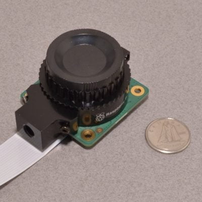
Raspberry Pi NoIR Camera
$25.95
Availability:
In Stock
This Raspberry Pi camera features the same OVR5647 5 megapixel camera found in the Official Raspberry Pi Camera V1 with a few improvements. The field of view is 60 degrees and features adjustable focus.
Available
Description
This Raspberry Pi camera features the same OVR5647 5 megapixel camera found in the Official Raspberry Pi Camera V1 with a few improvements. The field of view is 60 degrees and features adjustable focus. The camera also features two mounting points for Infrared Spotlights – these mount directly to the camera and are powered from the Pi.
The camera itself measures 25 x 24mm and 28mm tall with a 145mm (~5.5 inch) cable. The cable will connect directly to any standard sized Raspberry Pi (A, B, A+, B+, 2, 3, 3A+, 3B+, or any of the Raspberry Pi 4)
Features
- Resolution: 5 Megapixel (2592x1944)
- Camera Dimensions: 25 x 24mm
- Camera Height: 19mm
- Focal Length : 3.6mm (adjustable)
- Designed for Raspberry Pi
- Cable Length: 145mm
- Video frame rate: 1080p 30fps (H.264 AVC) Up to 90 fps Video at VGA
- CCD size: 0.25˝
- Field of View: 60 degrees
- Image Sensor: OV5647
- Aperture (F): 1.8
Package Contents
- 1 x Raspberry Pi NoIR Camera
- 1 x 145mm Camera Cable
May We Also Suggest…
Warranty Policy
This product has a 30 Day Warranty from the date of delivery. The item must not be modified, abused, incorrectly hooked up, or used for purposes outside the original scope of design.
Return Policy
This product is returnable Within 14 Days of delivery for a store credit. Item must be unopened, unused, and in re-saleable condition.
More Information:
For more information on our Warranty and Return Policies, please consult our Terms of ServiceComments
There are no comments yet.
Related Products


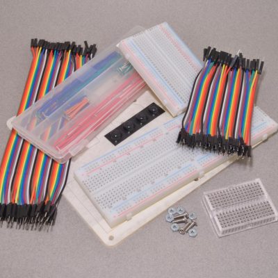
Raspberry Pi Pico H Starter Kit
$24.95
Brand:
Availability:
Low Stock - Only 1 Remaining
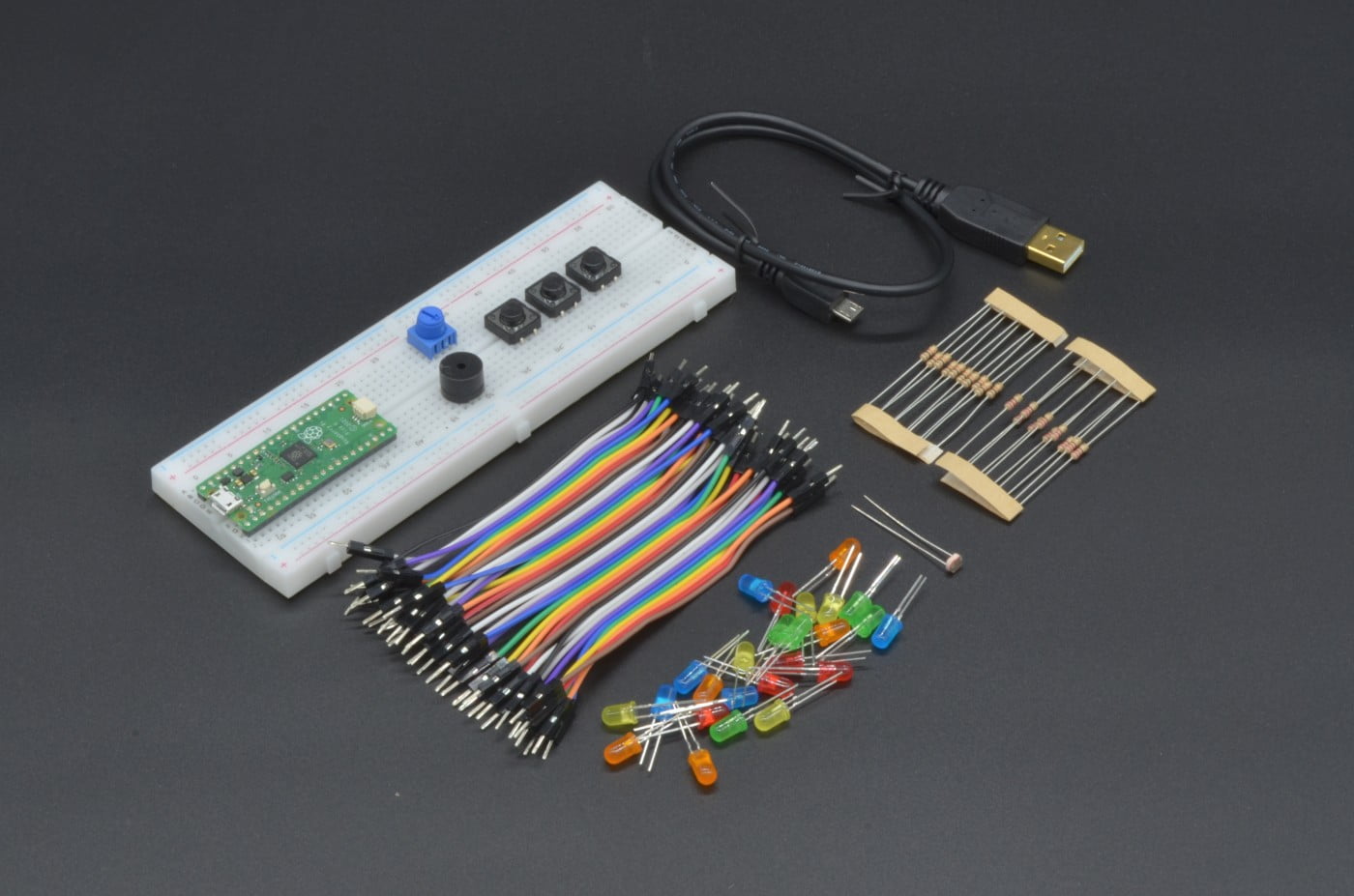
The Raspberry Pi Pico Starter Kit is a great way to get the Pico with all of the needed accessories to dive in to this new Microcontroller. The kit includes the Raspberry Pi Pico H, a programming cable, a large solderless breadboard, and a bunch of different components to experiment with – 55 pieces in total!
Available
Description
The Raspberry Pi Pico Starter Kit is a great way to get the Pico with all of the needed accessories to dive in to this new Microcontroller. The kit includes the Raspberry Pi Pico H, a programming cable, a large solderless breadboard, and a bunch of different components to experiment with – 55 pieces in total!
What is the Pico? The Raspberry Pi Pico is a low-cost, high-performance microcontroller board with flexible digital interfaces. It feature the RP2040 which marks Raspberry Pi’s first microcontroller designed in-house. Pico provides minimal (yet flexible) external circuitry to support the RP2040 chip (Flash, crystal, power supplies and decoupling and USB connector). The majority of the RP2040 microcontroller pins are brought to the user IO pins on the left and right edge of the board. Four RP2040 IO are used for internal functions – driving an LED, on-board Switched Mode Power Supply (SMPS) power control and sensing the system voltages.
Pico uses an on-board buck-boost SMPS which is able to generate the required 3.3 volts (to power RP2040 and external circuitry) from a wide range of input voltages (~1.8 to 5.5V). This allows significant flexibility in powering the unit from various sources such as a single Lithium-Ion cell, or 3 AA cells in series. Battery chargers can also be very easily integrated with the Pico power chain. Reprogramming the Pico’s flash memory can be done using USB (simply drag and drop a file onto the Pico which appears as a mass storage device) or via the Serial Wire Debug (SWD) port. The SWD port can also be used to interactively debug code running on the RP2040
Please Note: As of January 20th 2023, this kit now includes an assembled Pico H and no longer requires any soldering
Features
- Includes Raspberry Pi Pico H
- 55 Piece Kit
- No Soldering Required
Package Contents
- 1 x Raspberry Pi Pico H
- 1 x Large Solderless Breadboard
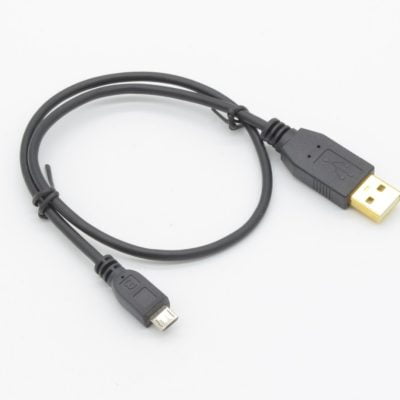
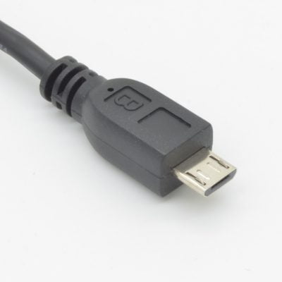
- 1 x 1.5′ USB A Male to Micro Cable
- 1 x 40pcs Premium Male/Male Jumper Wires
- 1 x 10K Trim Pot
- 1 x Passive Buzzer
- 3 x Large Tactile Button
- 5 x Yellow LED
- 5 x Orange LED
- 5 x Green LED
- 5 x Blue LED
- 5 x Red LED
- 10 x 10K Resistor
- 10 x 220 Ohm Resistor
- 1 x CDS Photocell
May We Also Suggest…
Tutorial
Product Tutorial: http://www.raspberrypi.org/documentation/pico/getting-startedOnline Guide
Online Guide: https://learn.adafruit.com/getting-started-with-raspberry-pi-pico-circuitpythonWarranty Policy
This product has a 30 Day Warranty from the date of delivery. The item must not be modified, abused, incorrectly hooked up, or used for purposes outside the original scope of design.
Return Policy
This product is returnable Within 14 Days of delivery for a store credit. Item must be unopened, unused, and in re-saleable condition.
More Information:
For more information on our Warranty and Return Policies, please consult our Terms of ServiceComments
There are no comments yet.
Related Products


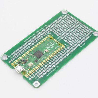
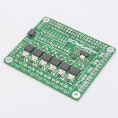
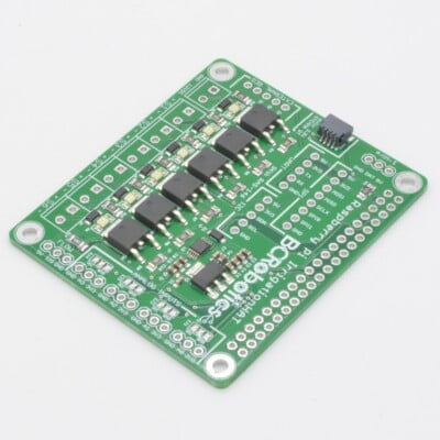
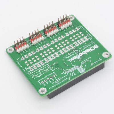
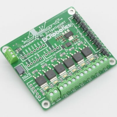
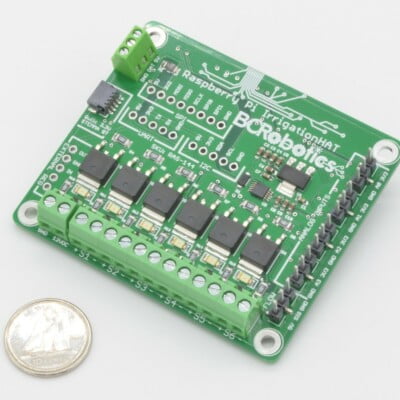
Raspberry Pi Pico Irrigation Board
$31.95
Brand:
Availability:
Temporarily Out Of Stock
Looking to build a Raspberry Pi Pico based smart irrigation system? The Raspberry Pi Pico Irrigation Board is just what you need! This board allows the Pico to operate with 12V power and control up to 5 solenoids (or other high current inductive loads) while providing numerous interfaces for sensors!
Out of Stock - Available on Backorder
Want to be notified when this product is back in stock?
Description
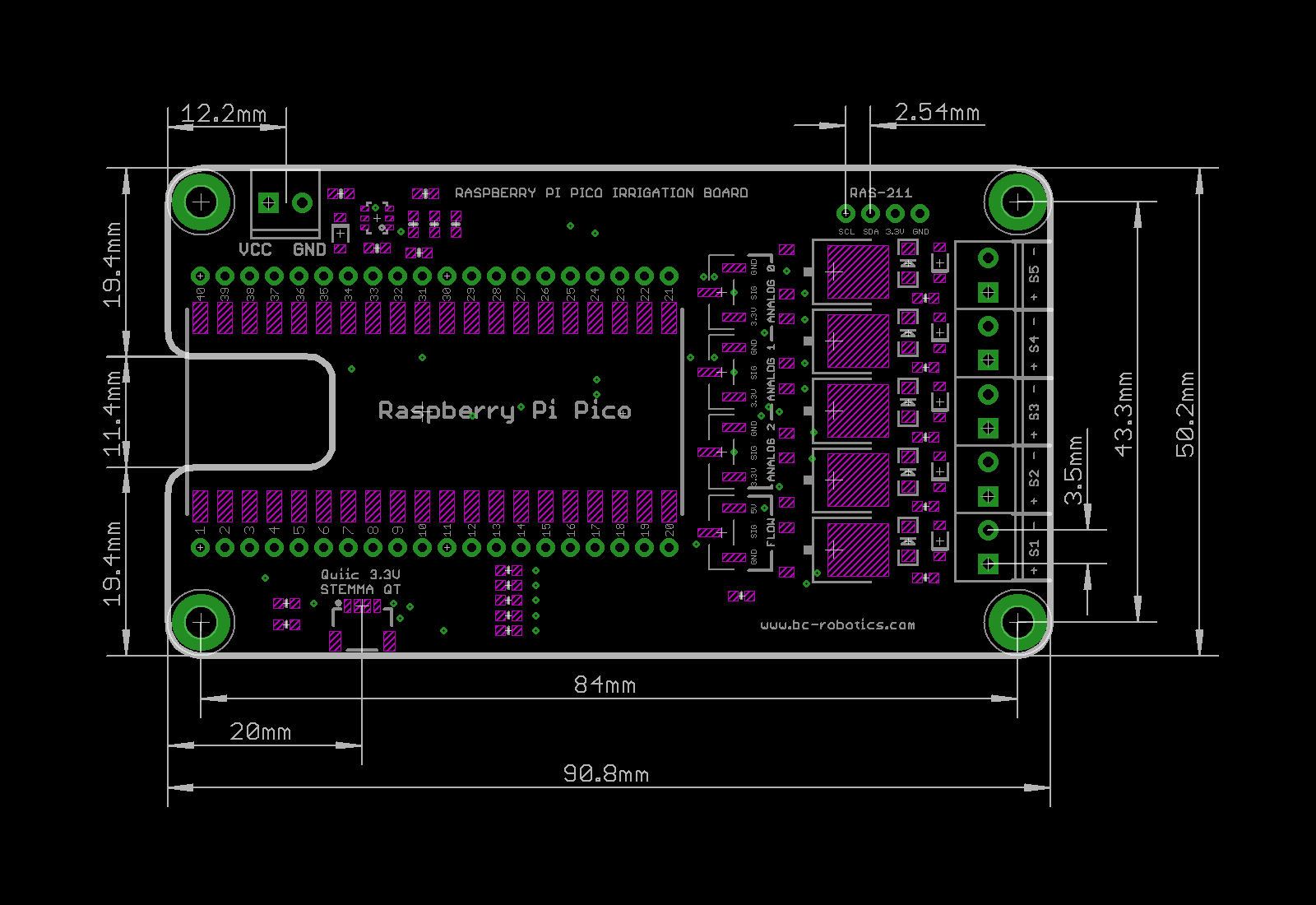
The Raspberry Pi Pico Irrigation Board is an all-in-one 5 channel MOSFET breakout complete with a DC power converter for the Raspberry Pi Pico and Pico W. This board allows the Pico to operate within a 12V system and switch high current inductive loads such as solenoids, pumps, or large relays. The Raspberry Pi Pico is connected using the castellated edges along the Pico, these are easily soldered with a conventional soldering iron. SMD Soldering Guide: https://learn.adafruit.com/adafruit-guide-excellent-soldering/surface-mount
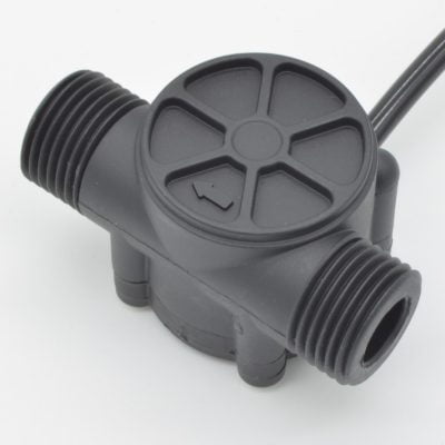
The board has 5 individually controlled driver circuits complete with an LED indicator showing when it is triggered and an integrated snub diode to protect your project from any power spikes caused by inductive loads. We have also included three connection points for analog sensors and a connection point for a flow sensor, compatible with any of our three wire flow sensors. To further extend functionality, we have also included a Qwiic / STEMMA QT connector, allowing any compatible breakout board or sensor to connect to the board.
Because this is designed for irrigation, we have added an extra feature to each of the analog inputs. Beside each of these analog channels is a solder jumper; this is used to choose your 3.3V source. By default this is set to the 3.3V power provided by an onboard regulator but we have also allowed each analog to be powered via a separate GPIO pin. This is done specifically for soil moisture sensors and helps prevent un-necessary corrosion caused when the sensor is powered in moist soil. Since the sensors draw a very tiny amount of voltage, they can be powered this way. Simply trip the connected GPIO pin HIGH and read the analog sensor, and turn off the pin.
Finally, we have an extra I2C connection point broken out to a 0.100″/2.54mm pitch footprint – great if you want to use larger I2C based soil moisture sensors like the Adafruit STEMMA Soil Moisture Sensor.
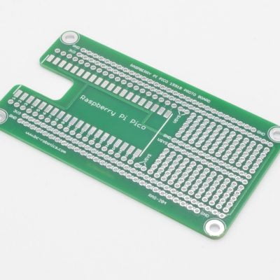
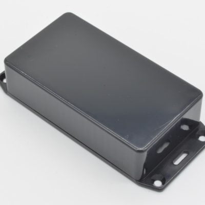
To make mounting as easy as possible, the Raspberry Pi Pico Irrigation Board is designed to fit in a standard Hammond 1591B enclosure.
Please Note: Raspberry Pi Pico is not included.
Features
- Input Voltage: 7 – 15VDC
- Qwiic / STEMMA QT connector
- Pico and Pico W compatible
- 5 Independent Control Circuits
- Compatible with Analog or I2C Soil Moisture Sensors
- Plug and Play flow sensor connection
- LEDs to indicate activated channels
- UL 94V-0 flammability rated PCB
Package Contents
- 1 x Raspberry Pi Pico Irrigation Board
May We Also Suggest…
Tutorial
Product Tutorial: https://bc-robotics.com/tutorials/getting-started-with-the-raspberry-pi-pico-irrigation-board/Mechanical Drawing
Mechanical Drawing: https://bc-robotics.com/wp-content/uploads/2024/03/raspberry-pi-pico-irrigation-board-drawing.pngWarranty Policy
This product has a 30 Day Warranty from the date of delivery. The item must not be modified, abused, incorrectly hooked up, or used for purposes outside the original scope of design.
Return Policy
This product is returnable Within 14 Days of delivery for a store credit. Item must be unopened, unused, and in re-saleable condition.
More Information:
For more information on our Warranty and Return Policies, please consult our Terms of ServiceComments
-
I’m a n00b, so this is probably a dumb question, but I don’t see any tutorials for thei Pi Pico Irrigation Board. Would the setup, coding, etc, for the regular Pi Irrigation Board still apply to this one? Also, will you restocking the the regular Pi Irrigation Boards? Thanks for the info!
-
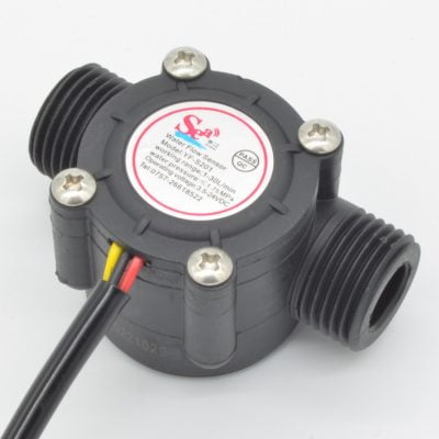
Liquid Flow Meter – YF-S201
$12.95 -
-
-
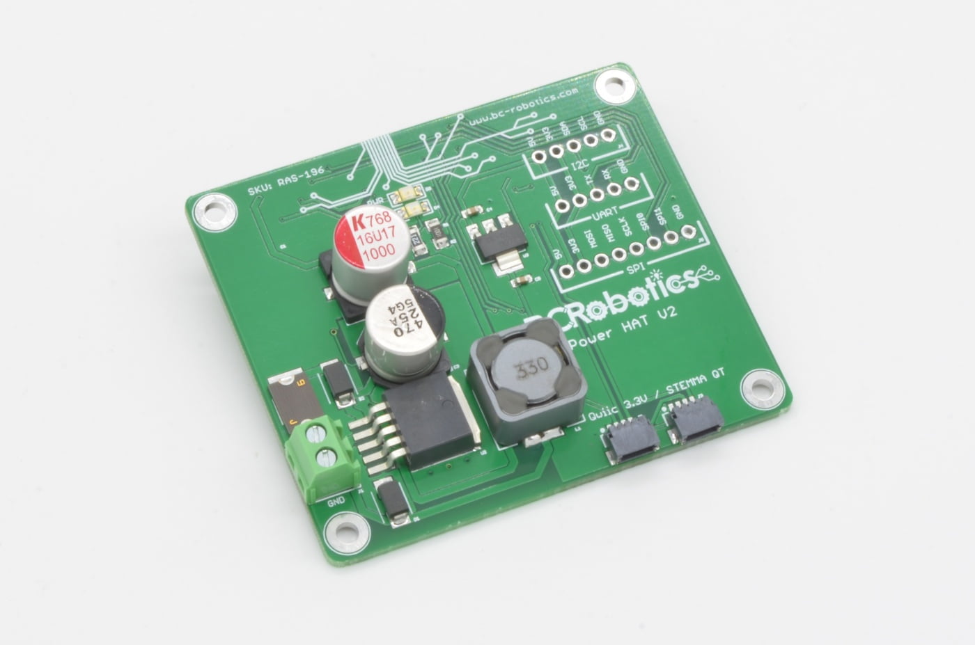


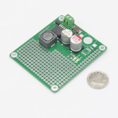
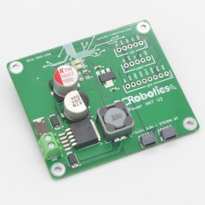
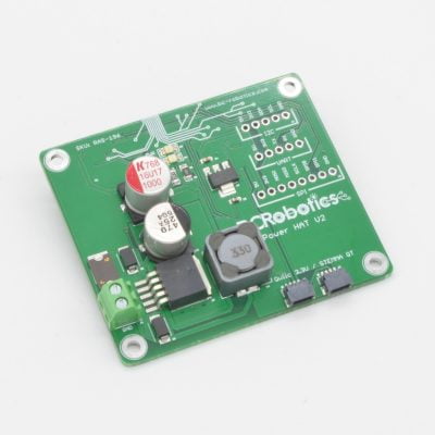
Raspberry Pi Power HAT v2 – Assembled
$24.95
Brand:
Availability:
Temporarily Out Of Stock
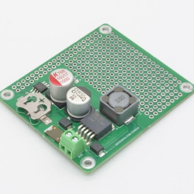
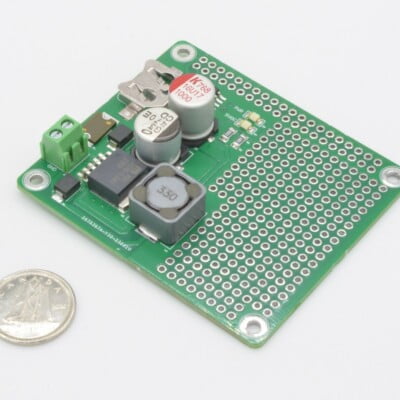
The Raspberry Pi Power HAT is an easy to use DC power converter for your Raspberry Pi! This board will take 7-16VDC and output 5V @ 3A to the Raspberry Pi by way of the GPIO header – a compact way to power your Pi.
Out of Stock - Available on Backorder
Want to be notified when this product is back in stock?
Description
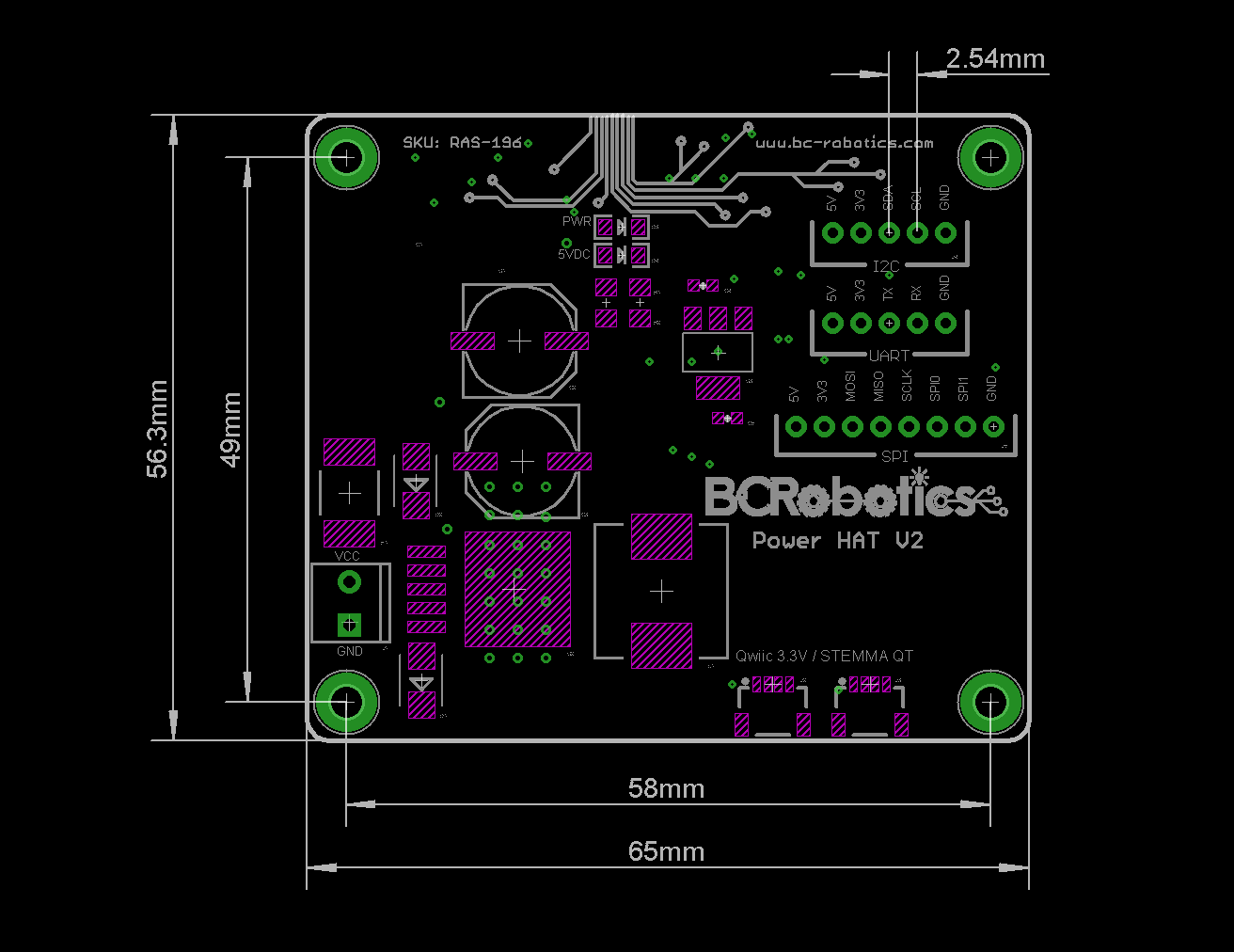
Need a simple way to power a Raspberry Pi from a DC source? This Raspberry Pi Power HAT solves this problem! Onboard is a fused and reverse polarity protected DC input coupled to a beefy 3A 5V DC/DC converter. Connected to a 12V automotive battery, this board is happy running the Pi under heavy load all day long.
To make this board even more useful, we have also included two SparkFun Qwiic / Adafruit STEMMA QT connectors – this is an easy-connect system for I2C sensors, actuators, shields using pre-built cables that make prototyping faster and less prone to error. Add sensors and further expand your Pi’s monitoring and control capabilities as you need, with no soldering required.
This version is fully assembled – no soldering required. Just hook it up and you are good to go! The board is compatible with all “A” and “B” versions of the Raspberry Pi (Pi A+, B+, 2, 3, 3A+, 3B+, and Pi 4)
Features
- Two STEMMA QT / Qwiic connectors
- 5V 3A Output to power Raspberry Pi
- Dimensions: 65 x 56mm
- Recommended Input: 7 - 16VDC
- Separate onboard 3.3V Regulator for Qwiic / STEMMA QT Bus
- Maximum Regulator Input: 36VDC
- UL 94V-0 flammability rated PCB
Package Contents
- 1 x Raspberry Pi Power HAT v2 - Assembled
May We Also Suggest…
Tutorial
Product Tutorial: https://bc-robotics.com/tutorials/getting-started-power-hats/Mechanical Drawing
Mechanical Drawing: https://bc-robotics.com/wp-content/uploads/2024/03/raspberry-pi-power-hat-assembled-drawing.pngWarranty Policy
This product has a 30 Day Warranty from the date of delivery. The item must not be modified, abused, incorrectly hooked up, or used for purposes outside the original scope of design.
Return Policy
This product is returnable Within 14 Days of delivery for a store credit. Item must be unopened, unused, and in re-saleable condition.
More Information:
For more information on our Warranty and Return Policies, please consult our Terms of ServiceComments
-
Though the recommended input is 7 – 16V the Max Reg Voltage is listed as 36V. Does this mean that it would work with an input of 24V from a 3D printer PSU, and, if so, would it have a reasonable lifespan? This seems like a neater solution than bodged USB cables and buck converters.
-
Hey Paul,
While the regulator is rated to 36V, this chip does get quite hot as you cross over 20V input at higher loads (greater than 1.5A continuous). If you were to address the heating, change / disable the PWR LED (it cant tolerate much more than ~18V with the current limiting resistor in place), and use it with a fairly stable input (the input cap is only rated to 35V) you could go over the 16V recommendation. Let us know if you have any additional questions!
-
-
Hi, recently bought one of these via Pi-Hut in the UK, and very happy so far.
But I have a question, I can’t find docs on this:
The Stemma/QT connectors, do they both connect to the same I2C bus, or is one on I2C-0 and the other on I2C-1?
Thanks and regards,
Richard
-
Hi Richard,
Thanks for the feedback! Both are connected to the same I2C bus; these were designed back when many of the StemmaQT / Qwiic boards were only providing one connector – making the chaining of the boards not possible. With that now changing on most boards, the two connectors have become a bit redundant in a way – unless you need sensors in opposite directions i guess. Let us know if you have any other questions 🙂
-
You may also like…
Related Products
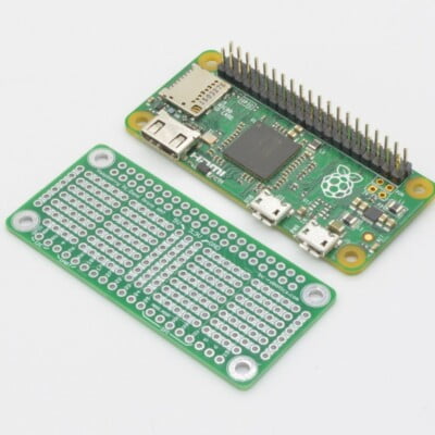
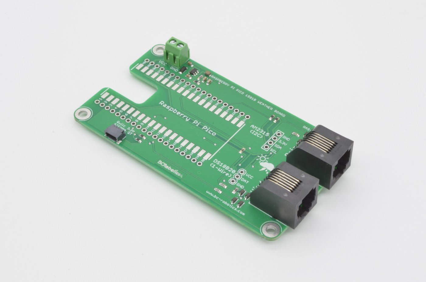


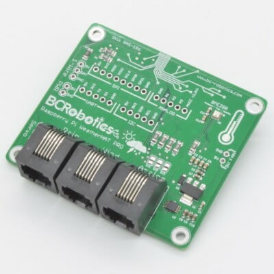
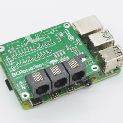
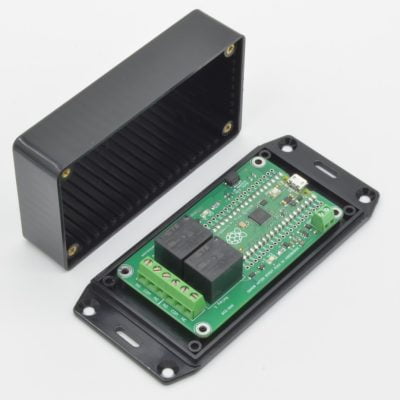
Raspberry Pi Pico 1591B Weather Board
$22.95
Brand:
Availability:
In Stock
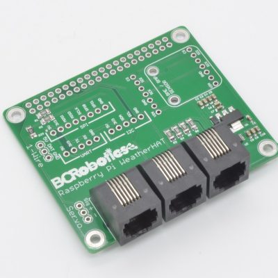
Looking to build a Raspberry Pi Pico based Weather Station? The Raspberry Pi Pico Weather Board is just what you need! This board allows the Pico to operate with 12V power and provides connections for weather meters, a temperature sensor, and any Qwiic / STEMMA QT sensors or modules.
Available
Description
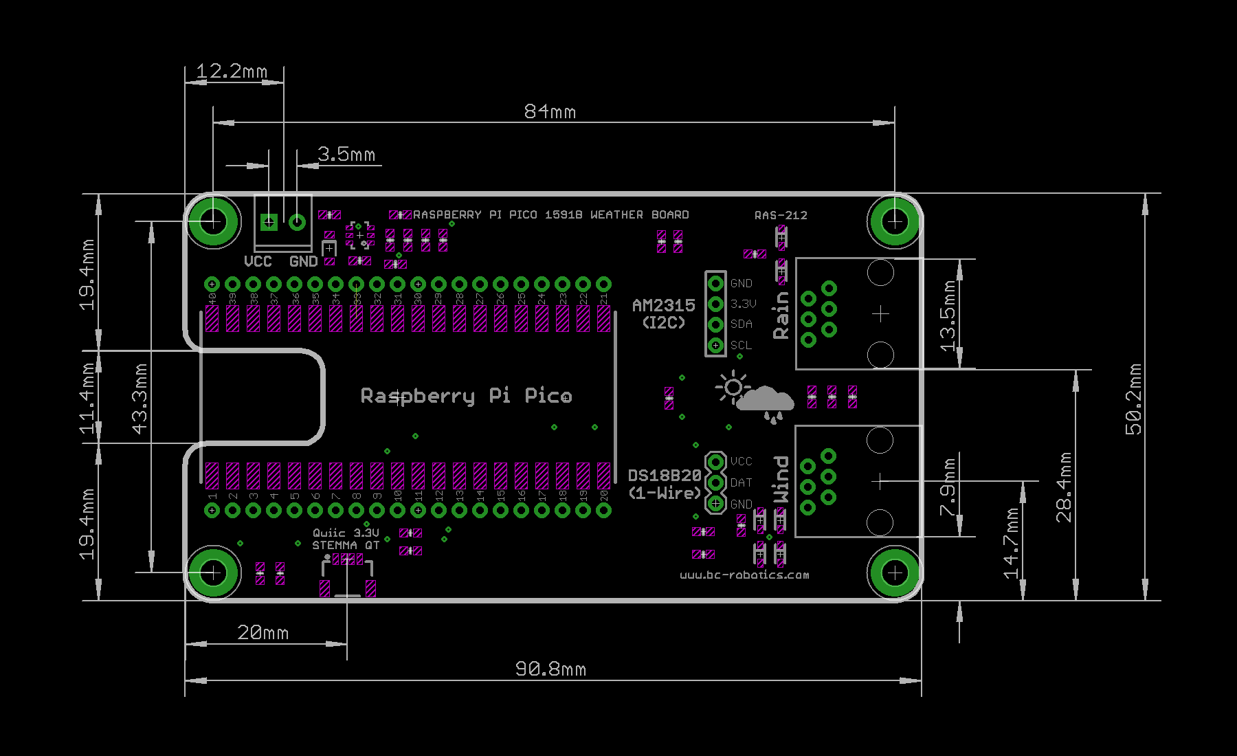
The Raspberry Pi Pico Weather Board is an all in one breakout board designed to turn your Raspberry Pi Pico or Pico W into a weather station. We have included connections and supporting circuitry for a number of popular additions including our Weather Meters, a DS18B20, and the AM2315. Additionally, we have a SparkFun Qwiic and Adafruit STEMMA QT connector onboard, meaning any compatible sensor or breakout can easily be connected. Perfect for adding a BME280 for Humidity / Pressure, a Light Sensor, UV Sensor, or whatever else you might need!
Because 5V isn’t always available, this board has an onboard DC/DC power converter, allowing the Pico to operate on voltages of 7-16VDC. To make mounting as easy as possible, the Raspberry Pi Pico Irrigation Board is designed to fit in a standard Hammond 1591B enclosure.
Please Note: Raspberry Pi Pico not included.
Features
- Input Voltage: 7 – 16VDC
- Qwiic / STEMMA QT connector
- Pico and Pico W compatible
- 2 x RJ11 Connectors (Weather Meters)
- 1 x 1-wire breakout
- 1 x i2c breakout
- UL 94V-0 flammability rated PCB
Package Contents
- 1 x Raspberry Pi Pico 1591B Weather Board
May We Also Suggest…
Tutorial
Product Tutorial: https://bc-robotics.com/tutorials/raspberry-pi-pico-weather-station-part-1/Mechanical Drawing
Mechanical Drawing: https://bc-robotics.com/wp-content/uploads/2024/03/raspberry-pi-pico-weather-board-drawing.pngWarranty Policy
This product has a 30 Day Warranty from the date of delivery. The item must not be modified, abused, incorrectly hooked up, or used for purposes outside the original scope of design.
Return Policy
This product is returnable Within 14 Days of delivery for a store credit. Item must be unopened, unused, and in re-saleable condition.
More Information:
For more information on our Warranty and Return Policies, please consult our Terms of ServiceComments
-
Hi, great board. It would be useful to have a pinout for the various connectors.
Thanks-
Hi Alex,
Thanks for the feedback – we will get that added to the resources
-
Related Products
-
-
Weather Meters
$139.95 -
-
-
Mike –
I can see a need for this. However, I don’t understand why the 40 pin header isn’t extended to allow for additional stacking HATs
Chris @ BCR –
Hi Mike, for that use case we recommend using the un-assembled version and adding the header you require: https://bc-robotics.com/shop/raspberry-pi-power-rtc-hat/
Chris B Olsen (verified owner) –
The UART breakout on the hat, where does this connect on the PI? Is it documented somewhere?
Thanks
William @ BC Robotics –
Hey Chris,
There is an tutorial coming for this board (and the Non-RTC version releasing today). The UART pins on the HAT connect directly to the UART pins on the GPIO header of the Pi. Quite literally a straight through connection
Chris B Olsen (verified owner) –
One more question.
Do you guys have any 3d models of this?
Working on a custom case in Fusion 360, would be handy
Chris @ BCR –
Unfortunately no 3D models are available
Cheers!